
Milling cutter system

A milling cutter and cutting tool technology, applied in the field of milling machine devices, can solve the problems of difficulty in ensuring the accuracy and high efficiency of the gun barrel rifling, rough surface of the female rifling with knife marks, large internal ballistic resistance, etc., and achieves strong flexibility and surface quality. Good, low ballistic resistance effect

Active Publication Date: 2018-03-23
DALIAN UNIV
View PDF6 Cites 0 Cited by
  • Summary
  • Abstract
  • Description
  • Claims
  • Application Information

AI Technical Summary

Problems solved by technology

But the production efficiency is low, the surface of the female rifling is rough and there are knife marks, the internal ballistic resistance after processing is large, the shape of the broach is complex and the manufacture is difficult
[0006] Therefore, the broaching method is difficult to guarantee the accuracy and high efficiency of the gun barrel rifling processing, and there are problems such as low productivity, low precision, and poor stability.

Method used


Image

  • Milling cutter system
  • Milling cutter system

Examples


Embodiment 1

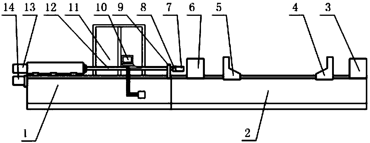
[0027] This embodiment provides a milling cutter system, comprising:

[0028] The bed 1 of the machine tool spindle is used to support the milling parts of the workpiece. The bed is provided with a roller linear guide for guiding during the milling process;

[0029] The machine tool spindle bed 1 is connected with a barrel bed 2, and the barrel bed 2 is used for barrel positioning and support for clamping parts, and a dovetail guide rail is set;

[0030] The body tube bed 2 is slidably connected with a front bracket 5, a rear bracket 4, a front fuel tank 6, and a rear fuel tank 3; wherein: the front bracket 5 and the rear bracket 4 are respectively fixedly connected with self-centering chucks for The positioning and clamping of barrel parts, the front oil tank 6 and the rear oil tank 3 are used for splash prevention and recovery of cooling oil;

[0031] The machine tool spindle bed 1 is connected with a fixed guide frame 9 and an operating table 10, the fixed guide frame 9 is...


PUM


Abstract

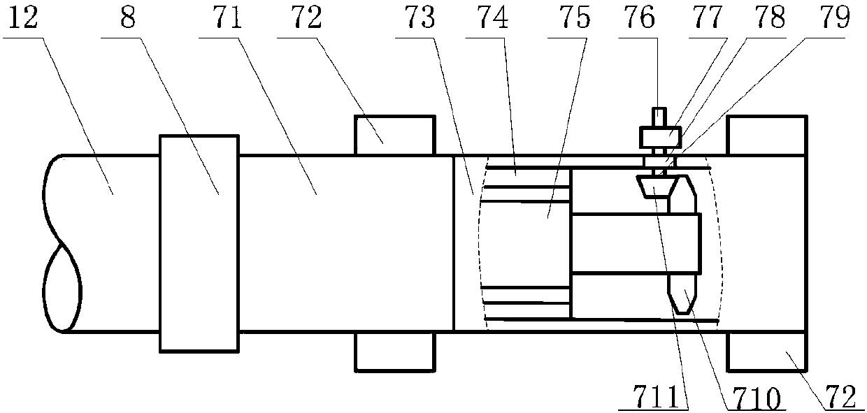
The invention belongs to the technical field of milling machine devices and specifically relates to a milling cutter system. The milling cutter system comprises a support cylinder, a spindle motor, cages, a main gear and a milling cutter apparatus. The support cylinder and a knife bar are connected through a flexible shaft coupling. Two ends of the support cylinder are both fixedly connected witha cage, which is used for keeping the support cylinder and the inner wall of a barrel to be contacted and keeping rotation center lines of the support cylinder and the barrel to be coaxial. A stator of the spindle motor is fixedly connected with the inner wall of the support cylinder. The main gear and a rotor are fixedly connected. Through the milling cutter, it is ensured that cross-section shape and size of barrel rifling are consistent, and changes of rifling depth and shape due to deformation of the knife bar by force will be avoided.

Description

[0001] This application is a divisional application with the application number 2017107297667, the application date of August 23, 2017, and the title of the invention "a CNC milling machine for rifling processing of artillery barrels". technical field [0002] The invention belongs to the technical field of milling machine devices, and in particular relates to a milling cutter system. Background technique [0003] Compared with smoothbore weapons, rifled weapons have high long-range accuracy, stable and convenient projectiles, and are suitable for different external ballistic requirements. It has been widely used since its invention. [0004] The specifications of the rifling include the structure and number of the rifling, the width of the male and female rifling, the depth of the female rifling, the winding degree of the rifling and other indicators; the rifling is divided into rectangle, trapezoid, circular arc, multi-arc, polygonal arc and bow according to the cross-sect...

Claims


Application Information

Patent Timeline
Patent Type & Authority Applications(China)
IPC IPC(8): B23C3/32
CPCB23C3/32
Inventor 王元刚吴蒙华王珍何利李晓鹏
Owner DALIAN UNIV
Learn More