Chip discharging structure of machine tool

A machine tool and chip flute technology, which is used in metal processing machinery parts, maintenance and safety accessories, metal processing equipment, etc. The effect of increasing the chip evacuation space, improving the smoothness of chip evacuation and improving the stability

Pending Publication Date: 2018-03-23
TAIZHOU EASTERN CNC EQUIP CO LTD
View PDF8 Cites 3 Cited by
  • Summary
  • Abstract
  • Description
  • Claims
  • Application Information

AI Technical Summary

Problems solved by technology

[0004] There are two problems in the existing flute: 1. The inclination angle is too small; 2. The width of the flute is small
The accumulation of these two problems will easily cause chips to block the chip removal groove and affect the chip removal speed

Method used


Image

  • Chip discharging structure of machine tool
  • Chip discharging structure of machine tool
  • Chip discharging structure of machine tool

Examples


Embodiment Construction

[0019] The following are specific embodiments of the present invention and in conjunction with the accompanying drawings, the technical solutions of the present invention are further described, but the present invention is not limited to these embodiments.

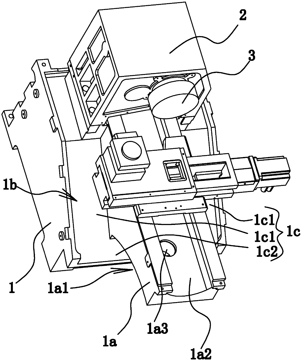
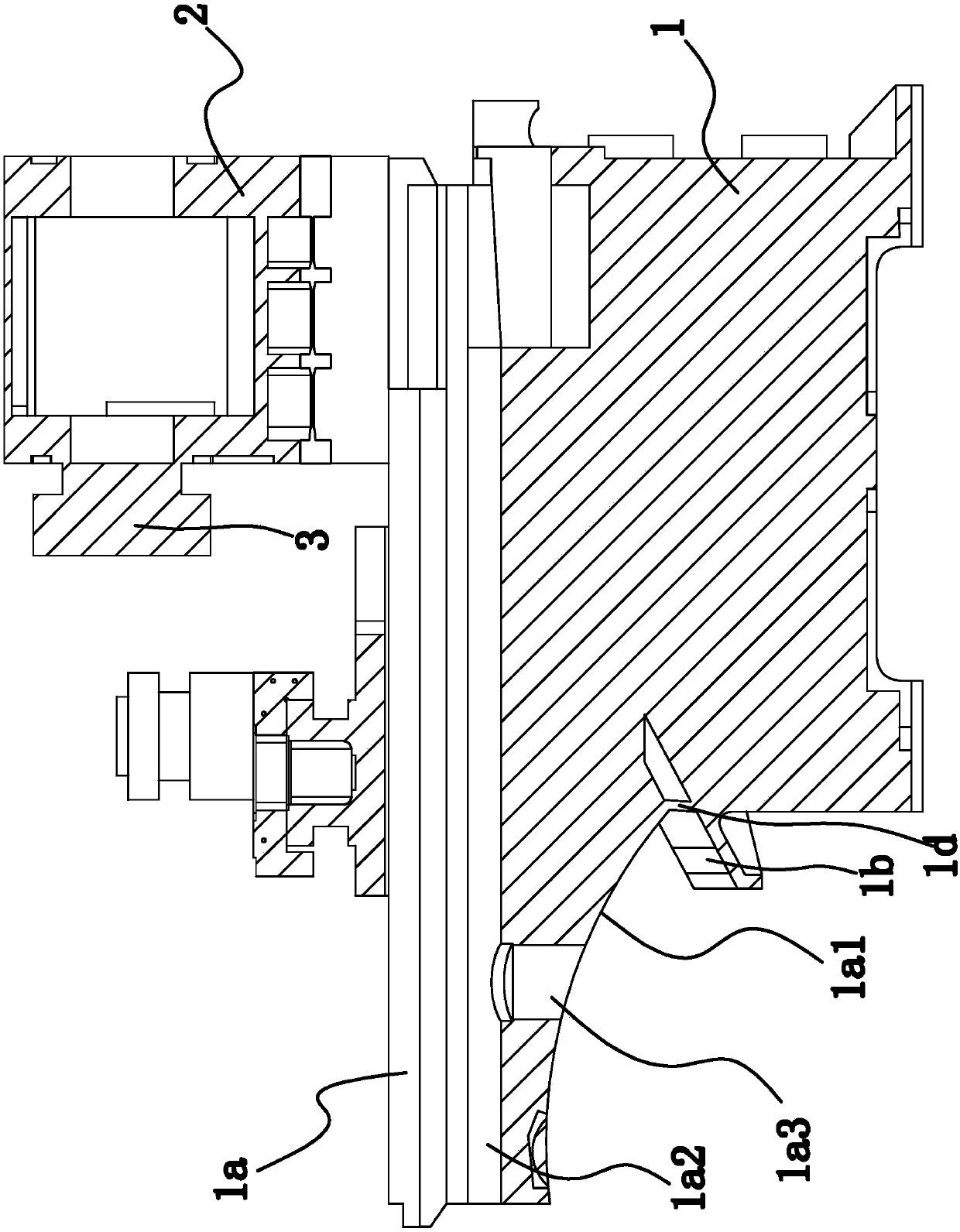
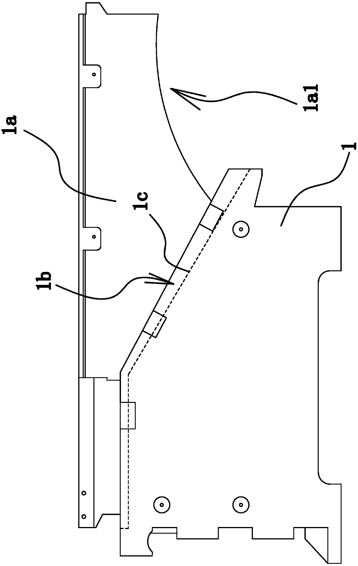
[0020] Such as Figure 1 to Figure 3 As shown, the machine tool includes a bed 1 and a headstock 2 arranged on the bed 1 , and a spindle 3 is installed on the headstock 2 . One side of the headstock 2 is provided with a strip-shaped installation platform 1a, and the installation platform 1a and the bed 1 are integrally structured. The mounting table 1 a is located directly below the main shaft 3 , and the length of the mounting table 1 a extends along the axial direction of the main shaft 3 . In actual use, the installation table 1a is used for installing guide rails.

[0021] Such as figure 1 and image 3 As shown, the chip removal structure includes a chip removal groove 1b provided on the bed 1, and the lower side o...


PUM


Abstract

The invention provides a chip discharging structure of a machine tool, and belongs to the technical field of machinery. The chip discharging structure solves the problem that an existing machine toolis not smooth in chip discharging. In the chip discharging structure of the machine tool, the machine tool comprises a tool body and a spindle box arranged on the tool body, one side of the spindle box is provided a mounting platform which is in a long strip shape and is used for mounting of guiding rails, and the mounting platform and the tool body are of an integrated structure; the chip discharging structure comprises a chip discharging groove formed in the tool body, the lower side of the mounting platform is located in the chip discharging groove, the bottom wall of the chip discharging groove is a first bevel, and the inclination angle of the first bevel is 30 degrees to 35 degrees; the first bevel is in a U shape and is composed of two first guiding surfaces and a second guiding surface, the two first guiding surfaces are correspondingly located on the two sides of the mounting platform, the second guiding surface is located between the two first guiding surfaces and is connected with the two first guiding surfaces, and the first guiding surfaces and the second guiding surface are each in a rectangular shape; and a circular-arc-shaped notch is formed in the lower side, awayfrom one end of the spindle box, of the mounting platform, the axis of the notch extends in the width direction of the mounting platform, and the notch directly faces the second guiding surface. The chip discharging structure of the machine tool has the advantages of smooth chip discharging.

Description

technical field [0001] The invention belongs to the technical field of machinery, and relates to a machine tool, in particular to a chip removal structure of the machine tool. Background technique [0002] The machine tool will produce a lot of cutting chips during processing. The cutting chips are easy to accumulate on the workbench or fall on the machine tool guide rail protective cover, and the cutting chips are difficult to clean. The accumulation of cutting chips will increase the load of the machine tool and deteriorate the dynamic performance. The guide rail protective cover Abrasion, deformation, or even damage, if not handled in time, will cause strain on the guide rail protective cover, which in turn will cause damage to the guide rail and loss of precision of the transmission screw. [0003] Existing machine tools generally consist of a bed, a spindle box, a spindle installed on the spindle box, a tool rest arranged on one side of the spindle, and the like. Where...

Claims


Application Information

Patent Timeline
Patent Type & Authority Applications(China)
IPC IPC(8): B23Q11/00
CPCB23Q11/0053
Inventor 赵玲刚
Owner TAIZHOU EASTERN CNC EQUIP CO LTD
Why Eureka
Try Eureka