
Magnetic levitation axial flow self-generating artificial heart pump

A technology of artificial heart and magnetic suspension shaft, which is applied in blood pump, medical science, hypodermic injection device, etc., to reduce the damage of blood cells, output power per unit volume, and improve stability.

Pending Publication Date: 2018-03-27
SHANDONG UNIV OF SCI & TECH
View PDF0 Cites 12 Cited by
  • Summary
  • Abstract
  • Description
  • Claims
  • Application Information

AI Technical Summary

Problems solved by technology

[0004] The purpose of the present invention is to overcome the shortcomings of the existing artificial heart pumps, comprehensively adopting magnetic levitation technology, bearingless switched reluctance technology, thermoelectric technology and ordinary motor technology, and propose a self-contained power generation device with strong battery life and high operation stability , A magnetic levitation axial flow self-generating artificial heart pump with low power loss, the technical solution is: a magnetic levitation axial flow self-generating artificial heart pump, including a levitation force stator, a rotating mechanism, a torque stator, a pump body, a blood channel, a return flow A power generation device and a waste heat power generation device; the inner cavity of the pump is provided with a torque stator, the torque stator includes a torque stator core and a torque winding, and the torque winding is wound on the torque stator core; the torque stator There are torque stator battery chambers at the upper and lower ends, and a built-in torque stator battery; the upper and lower ends of the pump body are respectively provided with a pump cover, the bottom middle of the lower pump cover is provided with a blood input port, and the top middle of the upper pump cover There is a blood output port at the position; the pump cover is provided with a levitation force stator battery cavity, and a levitation force stator battery is built in; the outer radially magnetized permanent magnet is embedded in the end of the pump cover; the pump cover is provided with four circumferential The connecting frame distributed in array connects the inside and outside of the pump cover into a whole through the connecting frame; the pump body and the pump cover are provided with mutually matching threads, which can disassemble and assemble the overall structure; the lower pump cover and the upper pump The suspension force stator and the rotation mechanism are arranged between the covers; the suspension force stator is located in the inner chamber of the rotation mechanism, and is pressed and fixed by the upper and lower pump covers. The suspension force stator includes the suspension force stator core and the suspension force winding, and the suspension force stator The force winding is wound on the stator core of the suspension force; the rotating mechanism is provided with a radial position adjustment ring, a magnetic isolation ring and a magnetic levitation rotor in sequence from the inside to the outside. The three are of the same height and are fixedly connected in sequence. The magnetic base and the inner radially magnetized permanent magnet, the inner radially magnetized permanent magnet is installed on the magnetic isolation base and is opposite to the same-sex magnetic pole of the outer radially magnetized permanent magnet; the shaft at the end of the pump cover is provided with a reflux power generation device; the rotor The inner side of the moment stator and the outer side of the suspension force stator are equipped with a ring-shaped waste heat power generation device

Method used


Image

  • Magnetic levitation axial flow self-generating artificial heart pump
  • Magnetic levitation axial flow self-generating artificial heart pump
  • Magnetic levitation axial flow self-generating artificial heart pump

Examples


Embodiment Construction

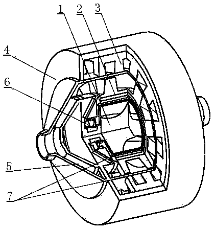
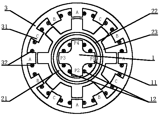
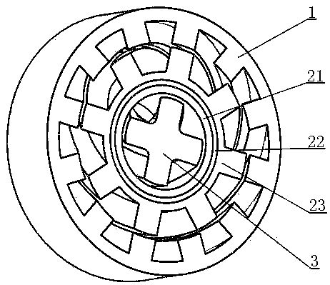
[0019] The present invention consists of seven parts: suspension force stator 1, rotating mechanism 2, torque stator 3, pump body 4, blood channel 5, backflow power generation device 6 and waste heat power generation device 7; the inner cavity of the pump body 4 is provided with a torque stator 3. The torque stator 3 includes a torque stator core 31 and a torque winding 32, and the torque winding 32 is wound on the torque stator core 31; the upper and lower ends of the torque stator 3 are provided with a torque stator battery chamber 44, the built-in torque stator battery 45 is used to supply power for the torque winding 32; the upper and lower ends of the pump body 4 are respectively provided with a pump cover 41, and the middle position of the bottom of the lower pump cover 411 is provided with a blood input port 53, and the upper The middle position of the top of the pump cover 412 is provided with a blood transfusion port 54; the pump cover 41 is provided with a suspension ...


PUM


Abstract

The invention relates to the field of artificial heat pumps and especially relates to a magnetic levitation axial flow self-generating artificial heart pump. The device comprises a suspension stator,a rotating mechanism, a torque stator, a pump body, a blood channel, a backflow generating device and waste heat generating devices; the torque stator is installed inside a pump body inner chamber; anupper end and a lower end of the torque stator are provided with torque stator storage battery chambers where a torque stator battery is internally installed; an upper end and a lower end of the pumpbody are provided with pump covers respectively; the upper pump cover and the lower pump cover are provided with a blood outlet and a blood inlet; the pump covers are provided with suspension statorbattery chambers where suspension stator batteries are internally installed; the suspension stator and the rotating mechanism are installed between the upper pump cover and the lower pump cover; a shaft of the pump cover end part is provided with a backflow generating device; the waste heat generating devices are installed inside the torque stator and outside the suspension stator. The present invention having self-generating device has strong endurance capability. The decoupling of the torque magnetic field and the levitation magnetic field is realized, the operation stability is high and the power loss is low; the blood pump function can be replaced by the human body instead of the heart for a long time.

Description

technical field [0001] The invention relates to the field of artificial heart pumps, in particular to a magnetic suspension axial flow self-generating artificial heart pump. Background technique [0002] Heart disease has always been an important cause of human death. Due to the lack of transplantable natural heart resources, the research and development of artificial hearts has gradually attracted widespread attention from experts and scholars at home and abroad. [0003] The research and development of the artificial heart began at the beginning of the 20th century, and it has undergone three major changes so far: the first generation of artificial heart pump was developed according to the physiological characteristics of the human heart. This kind of pump has complex structure, large volume, high energy consumption, easy to cause thrombus, and has great side effects on patients who receive artificial heart transplantation; Small size and large output flow, but due to the...

Claims


Application Information

Patent Timeline
IPC IPC(8): A61M1/10
CPCA61M2210/12A61M60/205A61M60/40A61M60/419
Inventor 孙传余李井凯宋政言徐特肖楠
Owner SHANDONG UNIV OF SCI & TECH
Learn More