Installation method for gantry structure of large-sized gantry machine tool

A technology of gantry machine tools and installation methods, which is applied in the direction of large fixed members, metal processing machinery parts, metal processing equipment, etc., can solve the problems of expensive laser interferometers, low verticality accuracy of X-axis guide rails, etc., to shorten the installation time, Reduce the dependence on quality and improve the effect of high adjustment accuracy

Active Publication Date: 2018-03-27
帝尔激光科技(无锡)有限公司
View PDF8 Cites 6 Cited by
  • Summary
  • Abstract
  • Description
  • Claims
  • Application Information

AI Technical Summary

Problems solved by technology

[0004] The invention provides a method for installing the gantry structure of a large-scale gantry machine tool, aiming to solve the problem of low verticality accuracy with the X-axis guide rail when using a square to install the Y-axis guide rail in the prior art and the high price when using a laser interferometer for installation. question

Method used


Image

  • Installation method for gantry structure of large-sized gantry machine tool
  • Installation method for gantry structure of large-sized gantry machine tool
  • Installation method for gantry structure of large-sized gantry machine tool

Examples


Embodiment 1

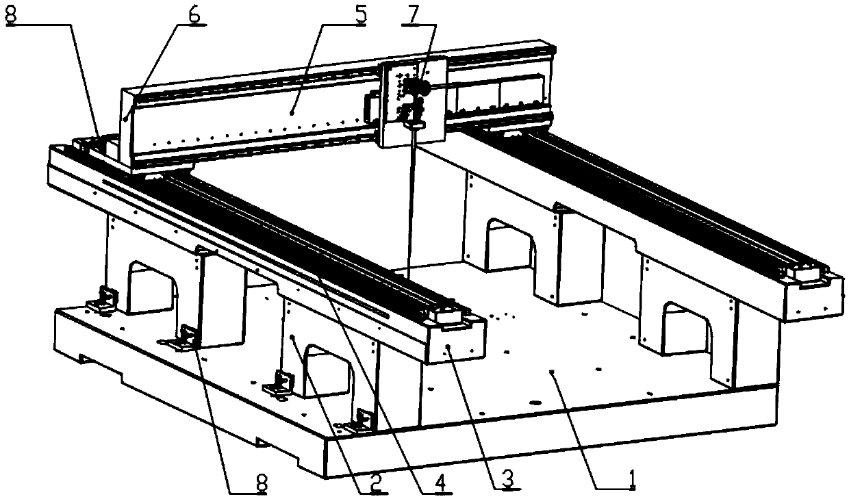
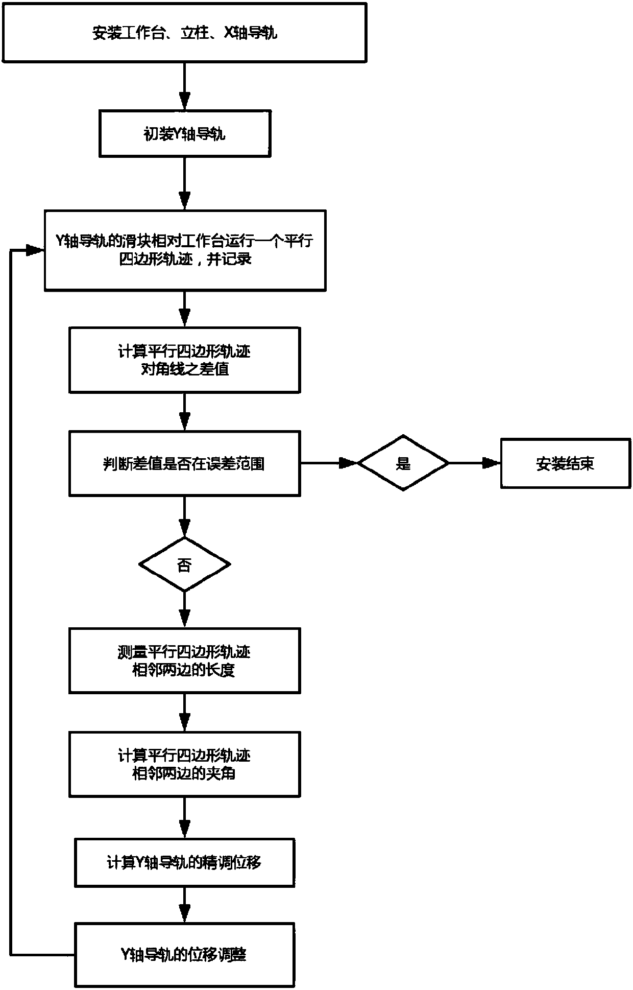
[0045] see figure 1 , this embodiment takes the bridge-type large-scale gantry machine tool as an example to introduce the installation method of its gantry structure. see figure 2 , the method includes the following steps.

[0046] Step 1: Installation of Workbench 1.

[0047] Install the workbench 1 on the ground, or install it on a corresponding machine base as required. The installation of the workbench 1 is carried out by a conventional installation method, and the flatness and levelness of the workbench 1 need to be ensured during installation.

[0048] As a large-scale gantry machine tool for precision machining, especially a large-scale gantry machine tool in the field of laser processing technology, the workbench 1 chooses a granite workbench that meets the national standard of GB / T20248-2006 rock slabs to ensure that it has a grade 0 stipulated by the national standard Or Class 1 flatness tolerance.

[0049]Adjustment of levelness is carried out by conventional...

Embodiment 2

[0105] Embodiment 2 is similar to the method of embodiment 1, but, when carrying out the fine adjustment of perpendicularity, can adopt such as Figure 4 The fine adjustment device 8 shown performs the adjustment.

[0106] The fine adjustment device 8 includes a pull plate. The pull plate is a pull plate with an L-shaped cross section, one end is a fixing portion 81 , and the other end is an adjusting portion 82 . Fix according to the parts that need to be adjusted. For example, when it is necessary to adjust the verticality of the Y-axis guide rail 5 and the X-axis guide rail 4, the fixing part 81 is fixed on the fixed surface of the Y-axis guide rail 5, or the fixing part 81 is fixed on the Y-axis On the fixed surface of the Y-axis beam 6 where the guide rail 5 is located, the adjusting part 82 is fixed on the Y-axis guide rail 5 to be adjusted or the Y-axis beam 6 .

[0107] The adjustment part 82 includes a push rod 83 and a pull rod 84. The push rod 83 is a threaded rod...

Embodiment 3

[0116] This embodiment takes the fixed beam type and the moving beam type large-scale gantry machine tools as examples to illustrate the installation method, which is similar to the second embodiment.

[0117] The difference is that the installation of the X-axis guide rail 4 is completed first, and the parallelism of the X-axis guide rail 4 is adjusted. Then, the workbench 1 is installed on the slider of the X-axis guide rail 4, and the levelness of the workbench 1 is tested. Adjust the levelness of the workbench 1 by plugging the gasket in the fixed part of the slide block between the table 1 and the X-axis guide rail 4. Then complete the installation of the Y-axis guide rail 5 .

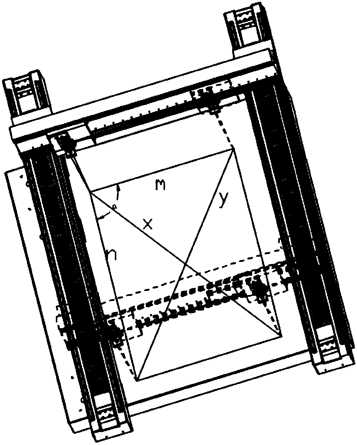
[0118] The difference lies in that when vertically adjusting the Y-axis guide rail 5 and the X-axis guide rail 4, the drawing method is different. Specifically, first move the slider of the Y-axis guide rail 5 to one end of the Y-axis guide rail 5, and the working table 1 Move to one end of the X...


PUM


Abstract

The invention provides an installation method for a gantry structure of a large-sized gantry machine tool. The installation method for the gantry structure of the large-sized gantry machine tool comprises the steps of installing a working table, vertical columns and an X axis guiding rail and installing a Y axis guiding rail; the step of installing the Y axis guiding rail comprises the processes of initial assembly and refined assembly; the initial assembly of the Y axis guiding rail is conducted according to the prior technology method; the refined assembly comprises the steps of enabling a sliding block of the Y axis guiding rail to move relatively to the working table to form a parallelogram-shaped trajectory, judging if the perpendicularity of the Y axis guiding rail and the X axis guiding rail reaches the requirement according to the relative error of the two diagonal lines of the parallelogram-shaped trajectory and finishing the installation if the requirement is reached; if therequirement is not reached, calculating the included angles, which are the included angles of the Y axis guiding rail and the X axis guiding rail, of adjacent two sides of the parallelogram-shaped trajectory according to the cosine law, obtaining the accurate adjustment displacement of the Y axis guiding rail by calculating according to the included angles and the length of the Y axis guiding rail, conducting the accurate adjustment of the Y axis guiding rail and finishing the installation. The installation method is simple, rapid and high-accuracy; a large amount of labor and time consumed bythe accurate adjustment and disassembly after the initial assembly in the prior art can be saved and the perpendicularity accuracy reaches up to 0.02mm.

Description

technical field [0001] The invention relates to a method for installing a gantry structure of a large-scale gantry machine tool, specifically provides a method capable of quickly installing the gantry structure of a large-scale gantry machine tool and improving installation accuracy, and belongs to the technical field of machine tool installation. Background technique [0002] With the development of the manufacturing industry, gantry machine tools have been used more and more, such as gantry milling machines, gantry punching machines, etc. In the field of laser processing technology, it has also been widely used in the technical fields of engraving, drilling, cutting and other processing of large-format materials. During processing, the large-format materials to be processed are fixed on the worktable, and the processing such as engraving, drilling, and cutting is completed through the relative movement of the processing head and the worktable. [0003] In modern processin...

Claims


Application Information

Patent Timeline
Patent Type & Authority Applications(China)
IPC IPC(8): B23Q1/01
CPCB23Q1/012B23Q1/015B23Q1/017
Inventor 李志刚宋久高
Owner 帝尔激光科技(无锡)有限公司
Why Eureka
Try Eureka