Sanitary deceleration transmission mechanism special for stirring

A deceleration transmission, sanitary technology, applied in the direction of transmission, transmission parts, gear transmission, etc., can solve the problems of long output shaft, easy aging of seals, easy distortion of hollow shaft, etc., to reduce volume, reduce The effect of wear and length reduction

Pending Publication Date: 2018-03-27
大连华辰化工机械有限公司 +1
View PDF1 Cites 0 Cited by
  • Summary
  • Abstract
  • Description
  • Claims
  • Application Information

AI Technical Summary

Problems solved by technology

The structure of the invention has the following deficiencies: 1. The dry well casing and the frame are split structures, and the dry well casing needs to be fixed on the frame through seals and bolts. The assembly process is complicated and the seal is used for a long time. 2. The hollow shaft is connected to the upper end of the output shaft for transmission movement, so a longer length of the output shaft is required for connection. The dry well sleeve is placed between the hollow shaft and the output shaft. This structure causes the output shaft to The length is lengthened, which causes the overall structure of the reduction transmission device to become larger; 3. Due to the length of the output shaft is too long, multiple

Method used


Image

  • Sanitary deceleration transmission mechanism special for stirring
  • Sanitary deceleration transmission mechanism special for stirring
  • Sanitary deceleration transmission mechanism special for stirring

Examples


Embodiment 1

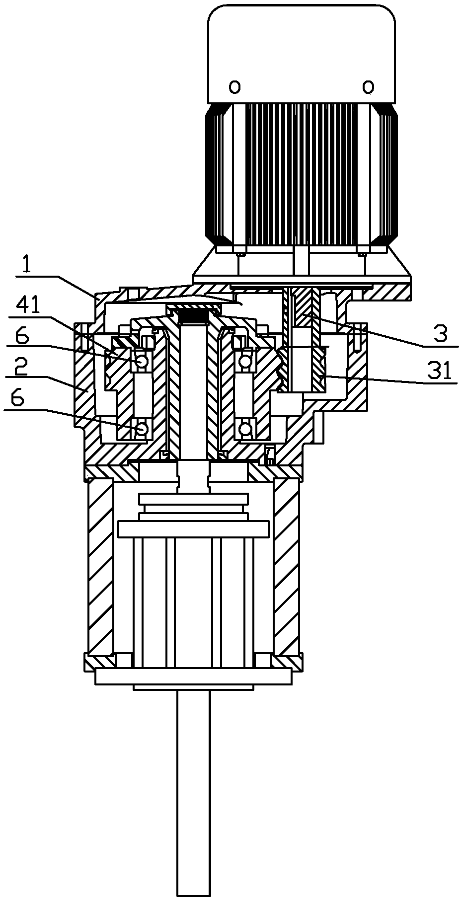
[0021] like figure 1 , figure 2 and image 3 As shown, a special deceleration transmission mechanism for hygienic stirring disclosed by the present invention includes a casing composed of an upper box 1 and a lower box 2, the upper box 1 and the lower box 2 are split structures, and the upper box 1 has a structure for fixing the driving motor, the driving motor is fixed on the upper box 1, the rotating shaft of the driving motor is connected with the input shaft 3 in the reduction transmission device through a structure such as a coupling, and the driving gear 31 is installed on the input shaft 3.

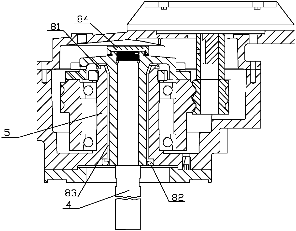
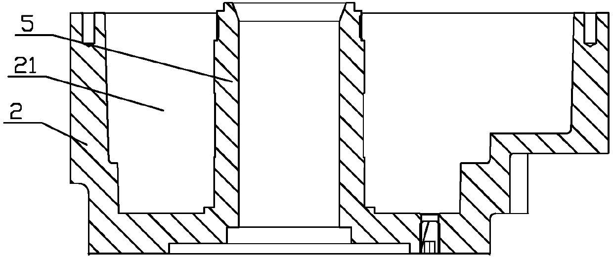
[0022] The lower casing 2 has a dry well casing 5 integrally cast with the sleeve structure, an oil storage tank 21 is formed between the dry well casing 5 and the lower casing 2, and the driving gear 31 and the driven gear 41 are placed in the oil storage tank 21 Inside, a bearing 6 is installed on the upper and lower ends of the outer wall of the dry well casing 5, and the dri...

Embodiment 2

[0029] A mixer includes a drive motor, a reduction transmission mechanism and a stirring wheel connected to the output shaft of the reduction transmission mechanism. The reduction transmission mechanism of the mixer adopts the reduction transmission mechanism of the integrated structure of the dry well casing and the chassis disclosed in the present invention.


PUM


Abstract

The invention discloses a deceleration transmission mechanism dedicated to hygienic stirring, which comprises a casing composed of an upper box body and a lower box body, an input shaft equipped with a driving gear, an output shaft equipped with a driven gear, the driving gear and the driven gear Gear meshing is used to drive the output shaft to rotate. The lower box has a dry well casing cast integrally with it. An oil storage tank is formed between the dry well casing and the lower box. The driving gear and the driven gear are placed in the oil storage tank. The dry well Bearings are installed on the outer wall of the sleeve, and the driven gear is installed on the dry well casing through the bearing. The driven gear is connected to the output shaft through the output shaft support arm. The output shaft support arm includes a gear connection part connected to the upper end of the driven gear, an extension The support part and the transition part that fit closely with the upper end of the output shaft into the inner diameter of the dry well casing. The reduction transmission mechanism has the advantages of small size, simple structure, good oil leakage prevention effect and the like.

Description

technical field [0001] The invention relates to a deceleration transmission mechanism dedicated to hygienic stirring. Background technique [0002] The general reduction transmission is usually sealed with a skeleton oil seal, which seals the lubricating oil placed in the reduction transmission to prevent oil leakage. However, during the working process of the deceleration transmission device, the long-term friction between the skeleton oil seal and the shaft is likely to cause wear of the skeleton oil seal, or the skeleton oil seal is aging due to long-term work, which will cause oil leakage, thereby affecting the life of the deceleration transmission device or cause product contamination. [0003] In order to solve this problem, Chinese Patent: Patent No.: 200720151973.0, Invention Name: An oil leakage prevention device for a reducer, discloses a device that uses a dry well casing to isolate the lubricating oil in the reducer from the output shaft to achieve the leak prev...

Claims


Application Information

Patent Timeline
IPC IPC(8): F16H1/08F16H57/029F16H57/023F16H57/04
CPCF16H1/08F16H57/023F16H57/029F16H57/0427
Inventor 杨意付春宏
Owner 大连华辰化工机械有限公司
Why Eureka
Try Eureka