
Electromagnetic induction-based calibrating device and method for cyclotron magnetic testing system

A cyclotron, electromagnetic induction technology, applied in measuring devices, instruments, measuring electrical variables, etc., can solve the problems of inaccurate test results, achieve the effect of compact structure, reduce test errors, and measure accurate

Pending Publication Date: 2018-03-27
HEFEI CAS ION MEDICAL & TECHNICAL DEVICES CO LTD
View PDF5 Cites 2 Cited by
  • Summary
  • Abstract
  • Description
  • Claims
  • Application Information

AI Technical Summary

Problems solved by technology

In recent years, the more commonly used test method is based on the electromagnetic induction principle of the detection coil, but each coil will cause inaccurate test results due to the difference in the winding process

Method used


Image

  • Electromagnetic induction-based calibrating device and method for cyclotron magnetic testing system
  • Electromagnetic induction-based calibrating device and method for cyclotron magnetic testing system

Examples


Embodiment 1

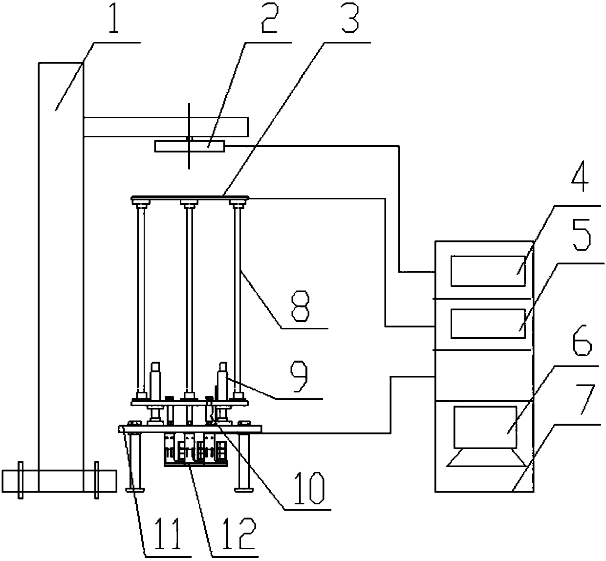
[0043] The present invention also provides a method for calibrating a cyclotron magnetic measurement system based on electromagnetic induction, the method comprising the following steps:

[0044] Step 1: Make preparations before the test: adjust the position of the test disc and the electrified wire disc to a suitable position, and the coil power supply loads a constant current for the electrified coil disc;

[0045] Step 2: Use the laser tracker to test the parallelism between the energized coil and the test disk. The accuracy requirement is 0.6mm. If the accuracy requirement is met, go to step 3. If the accuracy requirement is exceeded, adjust the parallelism to achieve the accuracy by padding Require;

[0046] Step 3: Number the detection coils from inside to outside, sequentially N1, N2, N3, ..., N20;

[0047] Step 4: Connect the detection coil N1 to the fluxmeter, and perform preheating, zero adjustment and drift adjustment on the fluxmeter;

[0048] Step 5: Control the...

Embodiment 2

[0053] The present invention also provides a method for calibrating a cyclotron magnetic measurement system based on electromagnetic induction, the method comprising the following steps:

[0054] Step 1: Make preparations before the test: adjust the position of the test disc and the electrified wire disc to a suitable position, and the coil power supply loads a constant current for the electrified coil disc;

[0055] Step 2: Use the laser tracker to test the parallelism between the energized coil and the test disk. The accuracy requirement is 0.6mm. If the accuracy requirement is met, go to step 3. If the accuracy requirement is exceeded, adjust the parallelism to achieve the accuracy by padding Require;

[0056] Step 3: Number the detection coils from inside to outside, sequentially N1, N2, N3, ..., N20;

[0057] Step 4: Connect 20 detection coils to 20 fluxmeters respectively, and perform preheating, zero adjustment and drift adjustment on all 20 fluxmeters;

[0058] Step ...


PUM


Abstract

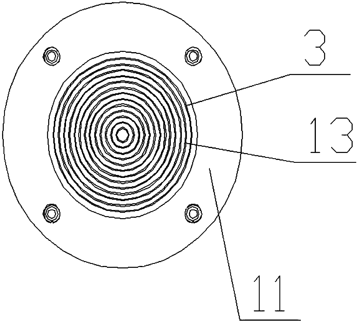
The invention discloses an electromagnetic induction-based calibrating device for a cyclotron magnetic testing system. The calibrating device comprises a driving mechanism and a detection mechanism mounted above the driving mechanism; the detection mechanism comprises a detection rack and a detection wire coil arranged above the detection rack, an electrified wire coil panel is arranged above thedetection wire coil and is connected with a wire coil power source, and the detection wire coil is connected with a fluxmeter. The invention also provides an electromagnetic induction-based calibrating method for the cyclotron magnetic testing system. The method comprises the following steps: a step of doing preparation work, a step of obtaining testing parallelism, a step of obtaining a serial number, and a step of collecting a magnetic induction intensity value; calibration results are analyzed and processed. The electromagnetic induction-based calibrating device and method are advantaged bycompact structure, simple operation, precise measurement, automatic collection of data and the like; measuring precision of the detection wire coil can be improved via calibration, testing errors canbe reduced, and the electromagnetic induction-based calibrating device and method are of vital importance in the field of nuclear medicine.

Description

technical field [0001] The invention belongs to the field of calibration and calibration for magnetic field measurement, in particular to a calibration device and method for realizing a cyclotron magnetic measurement system based on electromagnetic induction. Background technique [0002] Cyclotrons are widely used in the field of nuclear medicine, especially in the fields of radiopharmaceuticals and tumor treatment. It can realize the treatment of tumors with protons and heavy ion rays in the microscopic world. It is the most advanced radiation therapy technology in the world today, and only a few developed countries have mastered and applied this technology. [0003] The magnetic field of the superconducting cyclotron is mainly provided by the main magnet at room temperature and the superconducting coil. It is a very important part of the cyclotron. The magnetic field of the accelerator provides the binding force and strong focusing force for the movement of the beam, and ...

Claims


Application Information

Patent Timeline
Patent Type & Authority Applications(China)
IPC IPC(8): G01R35/00
CPCG01R33/0023
Inventor 宋云涛徐曼曼毕延芳金小飞李恒博王军冯汉升陈永华陈根杨庆喜丁开忠
Owner HEFEI CAS ION MEDICAL & TECHNICAL DEVICES CO LTD
Learn More