Control system and control method for highest control temperature of energy storage water tank

A technology for temperature control and energy storage water tanks, which is applied in the direction of using electric methods for temperature control, auxiliary controllers with auxiliary heating devices, etc. Problems such as the temperature cannot be raised and equipment investment is increased, so as to achieve the effects of reducing pollutant emissions, good economic benefits, and improving operating efficiency

Active Publication Date: 2018-03-27
HEBEI INSTITUTE OF ARCHITECTURE AND CIVIL ENGINEERING
View PDF4 Cites 0 Cited by
  • Summary
  • Abstract
  • Description
  • Claims
  • Application Information

AI Technical Summary

Problems solved by technology

In the process of heating water by the electric heater, in order to keep the temperature of the water heated by the heating container not exceeding the safety limit, there must be a certain difference between the inlet and outlet water temperatures of the electric heater, and the outlet water temperature of the heat storage tank cannot be raised to the maximum heat storage temperature. temperature, so the water temperature in the storage tank cannot be raised to the maximum
At present, the way to achieve the set heat storage temperature is to set a higher unloading temperature, but the increase of the unloading temperature means that the pressure requirements of the water tank and the heater are increased, the equipment investment is increased, and there are safety hazards

Method used


Image

  • Control system and control method for highest control temperature of energy storage water tank
  • Control system and control method for highest control temperature of energy storage water tank

Examples


Embodiment Construction

[0044] Below, the present invention is described in detail with reference to accompanying drawing and embodiment:

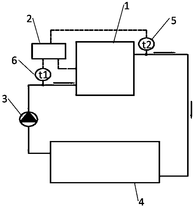
[0045] Such as figure 1 As shown, a control system for controlling the maximum temperature of an energy storage water tank includes a heat storage tank 4, the water inlet of the heat storage tank 4 communicates with the water outlet of the electric heater 1 through a pipeline, and the water storage tank 4 The water outlet of the tank 4 is communicated with the circulating water pump 3, and the other end of the circulating water pump 3 is communicated with the water return port of the electric heater 1, and an electric heater outlet water temperature sensor 5 is arranged in the outlet pipe of the electric heater 1, so that An electric heater return water temperature sensor 6 is arranged in the return water pipe of the electric heater 1 , and the electric heater outlet water temperature sensor 5 and the electric heater return water temperature sensor 6 transmit the...


PUM


Abstract

The invention discloses a control system and control method for highest control temperature of an energy storage water tank. The control system includes a heat storage water tank. A water inlet of theheat storage water tank is connected with a water outlet of an electric heater through a pipeline. A water outlet of the heat storage water tank is connected with a circulating water pump. The otherend of the circulating water pump is connected with a water return port of the electric heater. A water outlet pipe of the electric heater is provided with an electric heater water outlet water temperature sensor. An electric heater return water temperature sensor is arranged in a water return pipe of the electric heater. The electric heater water outlet water temperature sensor and the electric heater return water temperature sensor transmit measurement temperature to a controller. The control method includes steps of measuring the power of the electric heater, starting the heater, measuringinlet and outlet water temperature of the heat storage water tank, increasing the heat storage temperature and stopping heat storage. By adopting the system and method provided by the invention, unnecessary energy consumption is reduced, and operation safety and stability are enhanced. Further, device service lifetime is prolonged and manual operation is reduced.

Description

technical field [0001] The invention belongs to the field of electric control systems, and in particular relates to a control system for controlling the maximum temperature of an energy storage water tank and a control method thereof. Background technique [0002] The heat storage system uses electric heaters and heat storage devices as heat sources to provide heat to heat-consuming units. During the off-peak power period, the heat produced by the heater is stored by the heat storage device, and during the peak power period, the heat storage device supplies heat to the heat user. [0003] At the end of the heat storage period, the high-temperature stored hot water enters the heater for continuous heating. If the water temperature rises to the saturation temperature of the water in the electric heater or the water storage tank, a large amount of water will gasify, resulting in rapid pressure in the heat storage tank or the electric heater. If it exceeds the pressure capacity...

Claims


Application Information

Patent Timeline
IPC IPC(8): G05D23/30
CPCG05D23/30
Inventor 师涌江郑惠丹孔婵鲜沐希徐峰程鹏月刘锦王倩
Owner HEBEI INSTITUTE OF ARCHITECTURE AND CIVIL ENGINEERING
Why Eureka
Try Eureka