Continuous halving double-antipodal-type magnetic system permanent magnet high-gradient strong magnetic separation device

A counterpolar, high-gradient technology, applied in high-gradient magnetic separators, magnetic separation, solid separation, etc., can solve the problems of low magnetic field strength, non-continuous operation, and narrow separation space, so as to achieve uniform magnetic field strength and prevent Flux leakage phenomenon, the effect of improving the throughput

Active Publication Date: 2018-03-30
河北地质大学
View PDF6 Cites 2 Cited by
  • Summary
  • Abstract
  • Description
  • Claims
  • Application Information

AI Technical Summary

Problems solved by technology

In the above, the large permanent magnets are consolidated with the iron yoke to directly form the poles of the opposite pole closed magnetic system, and some use small permanent magnets to directly superimpose and extrude the magnetic poles to form the opposite pole closed magnetic system structure. Pole-type closed magnetic system structure still has relatively low magnetic field strength and narrow separation space in the separation of weak magnetic or extremely weak magnetic powder, and most of them are intermittent operations, which cannot be continuously operated.

Method used


Image

  • Continuous halving double-antipodal-type magnetic system permanent magnet high-gradient strong magnetic separation device
  • Continuous halving double-antipodal-type magnetic system permanent magnet high-gradient strong magnetic separation device
  • Continuous halving double-antipodal-type magnetic system permanent magnet high-gradient strong magnetic separation device

Examples


Embodiment Construction

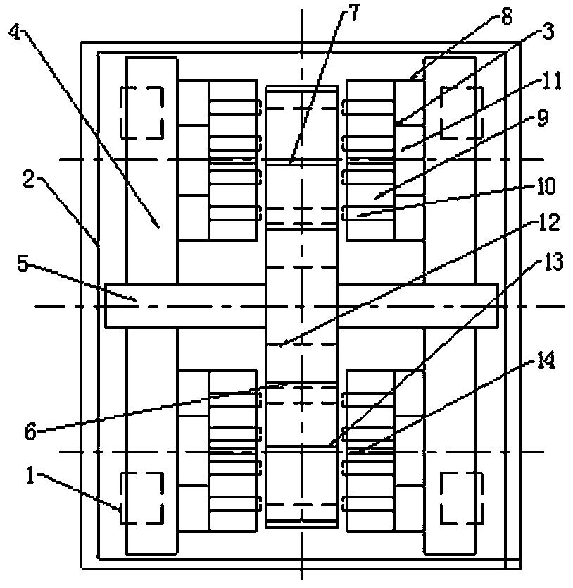
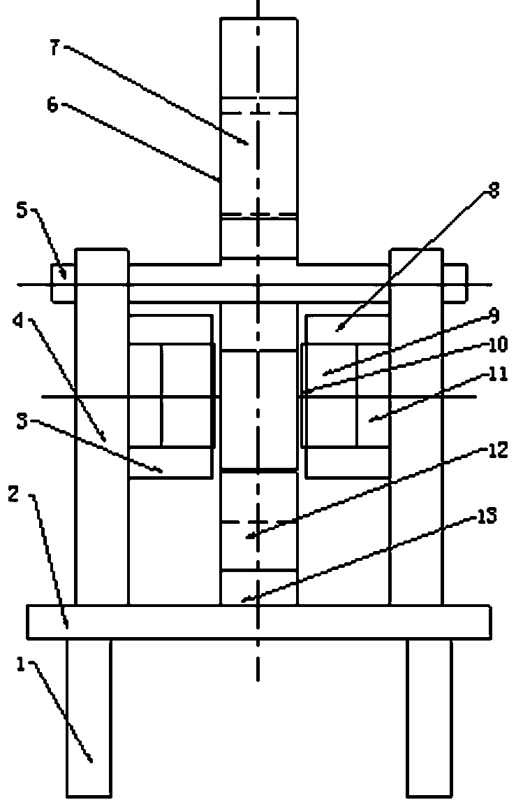
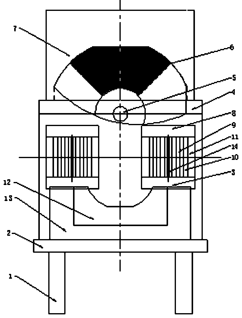
[0032] The present invention will be further described below in conjunction with embodiment (accompanying drawing):

[0033] like figure 1 , 2, 3, the magnetic system device of the present invention is mainly composed of a frame 1, a support platform 2, a square permanent magnet 3 for extruding the bottom, a magnetic system yoke 4, a rotating shaft 5, a magnetic gathering medium cylinder 6, and a feeding chute 7 1. Square permanent magnet for upper extrusion 8. One of several square permanent magnets for middle extrusion 9. One of several square soft iron magnetic poles for middle extrusion 10. Square permanent magnet for extrusion close to the yoke 11. Magnetic material The collection tank 12, the non-magnetic material collection tank 13, the square permanent magnet for extrusion in the middle, and the square soft iron magnetic pole group 14 for extrusion in the middle, etc.;

[0034] To be specific: the whole machine of the present invention adopts a center-divided double-...


PUM


Abstract

The invention discloses a continuous halving double-antipodal-type magnetic system permanent magnet high-gradient strong magnetic separation device. A rotating shaft is used as the center of the device, and the mode of symmetrically arranging magnet yokes of the same magnetic system is adopted to form complete machine front-back symmetrical magnetic poles of the antipodal-type structure. The radial center plane of a magnetism gathering medium barrel is used as a symmetry plane to form left-right halving-type symmetrical magnetic poles of the antipodal-type structure. The structural style of apolygon magnetism gathering medium barrel is adopted in the magnetism gathering medium barrel, and an inner cavity of the magnetism gathering medium barrel is divided into four regions with the same area symmetrically at the two sides of a perpendicular bisector of the magnetism gathering medium barrel in the length direction. Magnetism gathering media are symmetrically installed in the regions atthe two ends of the inner cavity of the magnetism gathering medium barrel, and the adjacent regions at the two sides of the perpendicular bisector refer to magnetism gathering medium-free regions. Square permanent magnets are adopted as the magnetic poles, and five-face square extrusion soft iron materials at the upper side, the lower side, the left side, the right side and the tail portion serveas the magnetic poles. The square soft iron materials are further used as magnetic pole guide magnetic force lines. The square soft iron magnetic poles with the five faces being extruded are symmetrically arranged to form the antipodal-type structure.

Description

technical field [0001] The invention relates to a permanent-magnet high-gradient magnetic separation device for weak magnetic powder. This magnetic separation device is especially suitable for dry separation of coarse coal powder, and can be widely used in energy, electric power, metallurgy, and non-metallic mineral purification and removal. miscellaneous fields. Background technique [0002] The magnetic separation device with opposite pole magnetic system structure is a closed magnetic circuit structure often used in today's permanent magnet strong magnetic separators. V. Zejurka and others from the Czech Republic abroad made a pair of multiple small permanent magnets in the Czech Republic. The magnetic field characteristics of the polar magnetic system structure have been measured systematically and the glaze material has been experimentally studied. The research results show that the closed structure of the opposite pole magnetic system designed with NdFeB permanent magn...

Claims


Application Information

Patent Timeline
Patent Type & Authority Applications(China)
IPC IPC(8): B03C1/029B03C1/033
CPCB03C1/029B03C1/0332
Inventor 刘鹏王吉中史长亮顾晓滨张旭惠兵马娇赵继芬杨炳飞张小伟
Owner 河北地质大学
Why Eureka
Try Eureka