Supercharge Your Innovation With Domain-Expert AI Agents!

Lubricating oil radiator installed in front of turbofan of aircraft engine

An aircraft engine and radiator technology, applied in the cooling of the engine, engine components, and cooling of the turbine/propulsion device, etc., can solve the problems of insufficient heat dissipation capacity of the radiator, induced air turbulence, and reduced space utilization. The effect of simple maintenance, energy saving and simple structure

Pending Publication Date: 2018-03-30
XIAMEN UNIV
View PDF0 Cites 0 Cited by
  • Summary
  • Abstract
  • Description
  • Claims
  • Application Information

AI Technical Summary

Problems solved by technology

Existing radiators have insufficient heat dissipation capacity when the aircraft is taxiing near the ground at low speed. Conventional radiators often induce problems such as incoming air turbulence and excessive air pressure drop, and traditional heat exchange and cooling devices are installed inside aircraft engines. A specific installation space is required, and the pipes connecting the inlet and outlet of the oil header are long and complicated. Some refrigerant pipes are added to increase the cooling effect, which greatly reduces the space utilization rate. Therefore, a design that can make full use of the incoming air and make full use of the limited space very necessary

Method used


Image

  • Lubricating oil radiator installed in front of turbofan of aircraft engine
  • Lubricating oil radiator installed in front of turbofan of aircraft engine
  • Lubricating oil radiator installed in front of turbofan of aircraft engine

Examples


Embodiment Construction

[0024] The content of the present invention is specifically described below in conjunction with accompanying drawing and embodiment:

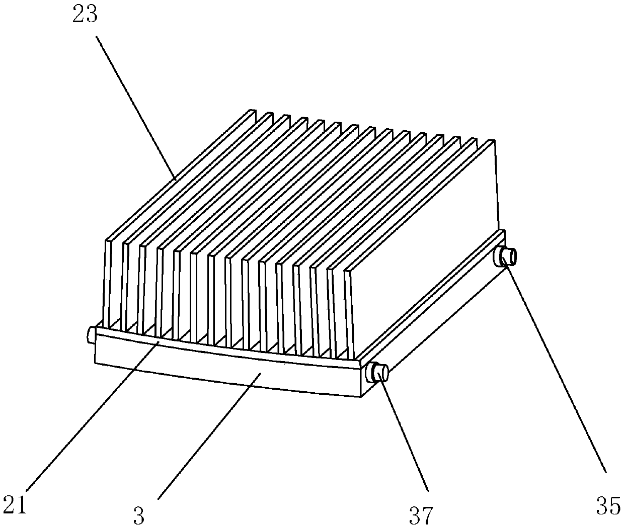
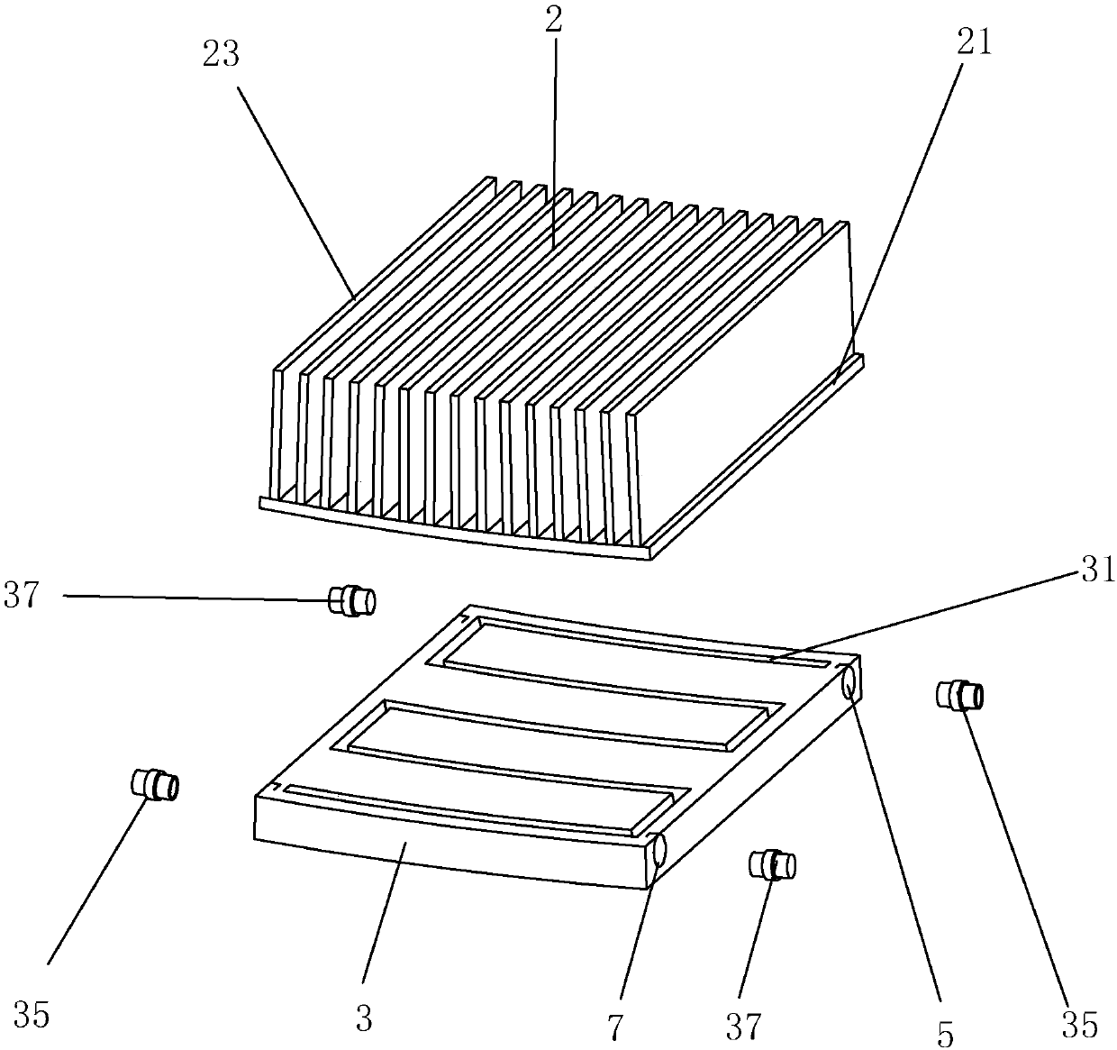
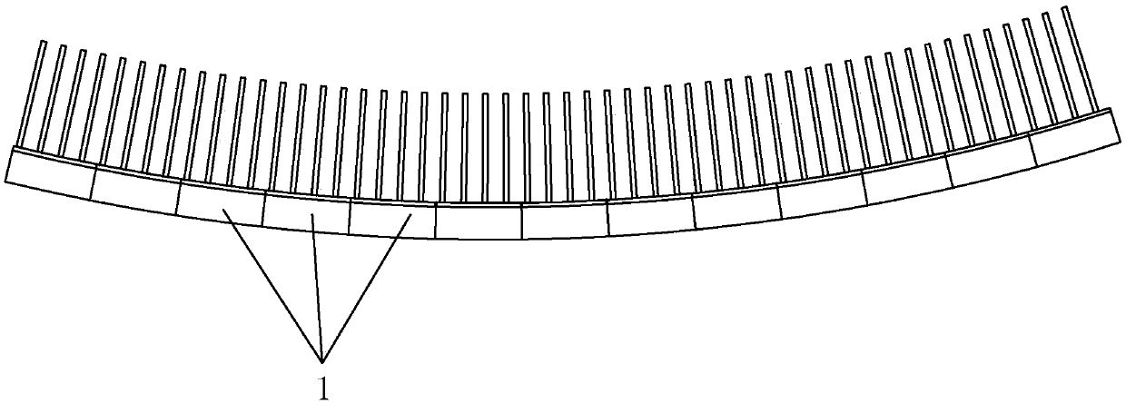
[0025] Please check Figure 1-3 , a kind of lubricating oil radiator installed in front of the turbofan of the aircraft engine of the present embodiment includes a plurality of radiator subunits 1;

[0026] The radiator subunit 1 includes an upper cover 2 and a base 3;

[0027] The upper cover 2 includes a cover plate 21 and a set of ribs, the cover plate 21 is an arc-shaped plate, the set of ribs is arranged on the side of the cover plate 21 facing the center of the circle, and includes a plurality of ribs 23, the The ribs 23 are perpendicular to the upper surface of the cover plate and arranged at intervals along the arc length direction of the cover plate, and an air duct is formed between the two adjacent ribs 23; when the aircraft taxis near the ground, the outside air flows through the air duct to form a natural Refrigerant, used to coo...


PUM


Abstract

The invention discloses a lubricating oil radiator installed in front of a turbofan of an aircraft engine. The lubricating oil radiator comprises a plurality of radiator subunits, wherein each radiator subunit comprises an upper cover and a base; each upper cover comprises a cover plate and a rib set; each base is provided with an inner flow channel; the two side walls of each base in the arc length direction are spliced surfaces; first connecting holes and second connecting holes are formed in the spliced surfaces; first connecting pieces and second connecting pieces are arranged on the spliced surfaces; the first connecting pieces and the second connecting pieces are used for splicing all the radiator subunits; the first connecting pieces are used for communicating the inner flow channels in the radiator subunits; and lubricating oil flows in through the first connecting piece of the initial radiator subunit, flows through the inner flow channels and then flows out through the firstconnecting piece of the tail end radiator subunit. According to the lubricating oil radiator installed in front of the turbofan of the aircraft engine, the multiple heat radiator subunits are connected into a whole, and cooling of the lubricating oil is carried out by fully utilizing the incoming flow of air; and the lubricating oil radiator has the advantages of being large in heat dissipation capacity, small in size, simple in structure and high in space utilization rate.

Description

technical field [0001] The invention relates to a lubricating oil radiator installed in front of a turbofan of an aircraft engine. Background technique [0002] Radiators are widely used in aerospace and other engineering heat dissipation fields. The design of the radiator is related to the operation stability and service life of construction machinery. Therefore, the innovative design of the heat sink is the key to improving the heat dissipation performance. [0003] When an aircraft is taxiing close to the ground, the engine system will generate enormous heat. In order to ensure the stability and reliability of aircraft system operation, it is necessary to cool down the engine system in time. The lubrication system can take away the heat of the aircraft gearbox and each bearing in time, and reduce the operating temperature of the lubricating oil system, usually using a conventional heat exchanger. Existing radiators have insufficient heat dissipation capacity when the ...

Claims


Application Information

Patent Timeline
Patent Type & Authority Applications(China)
IPC IPC(8): F02C7/14F02C7/18
CPCF02C7/14F02C7/18
Inventor 蔡惠坤廖亦戴翁泽钜
Owner XIAMEN UNIV
Features
  • R&D
  • Intellectual Property
  • Life Sciences
  • Materials
  • Tech Scout
  • Unparalleled Data Quality
  • Higher Quality Content
  • 60% Fewer Hallucinations
Learn More