Energy storage device for air compressor waste heat reuse

A technology of energy storage device and air compressor, which is applied in the direction of mechanical equipment, machine/engine, liquid variable capacity machinery, etc. It can solve the problems of thermal energy not being effectively used, not meeting energy saving requirements, waste, etc., and achieve temperature balance , Improve the utilization rate and avoid the effect of overheating

Active Publication Date: 2018-03-30
广东温博节能环保科技有限公司
View PDF6 Cites 3 Cited by
  • Summary
  • Abstract
  • Description
  • Claims
  • Application Information

AI Technical Summary

Problems solved by technology

The existing air compressor system mainly includes an air compressor, an oil-air separator and an oil cooler. During operation, the circulating cooling lubricating oil in the air compressor enters the oil cooler after passing through the oil-air separator, and is cooled by the oil cooler. Then it is recycled back into the air compressor. During the entire operation of the air compressor, about 90% o

Method used


Image

  • Energy storage device for air compressor waste heat reuse
  • Energy storage device for air compressor waste heat reuse

Examples


Embodiment 1

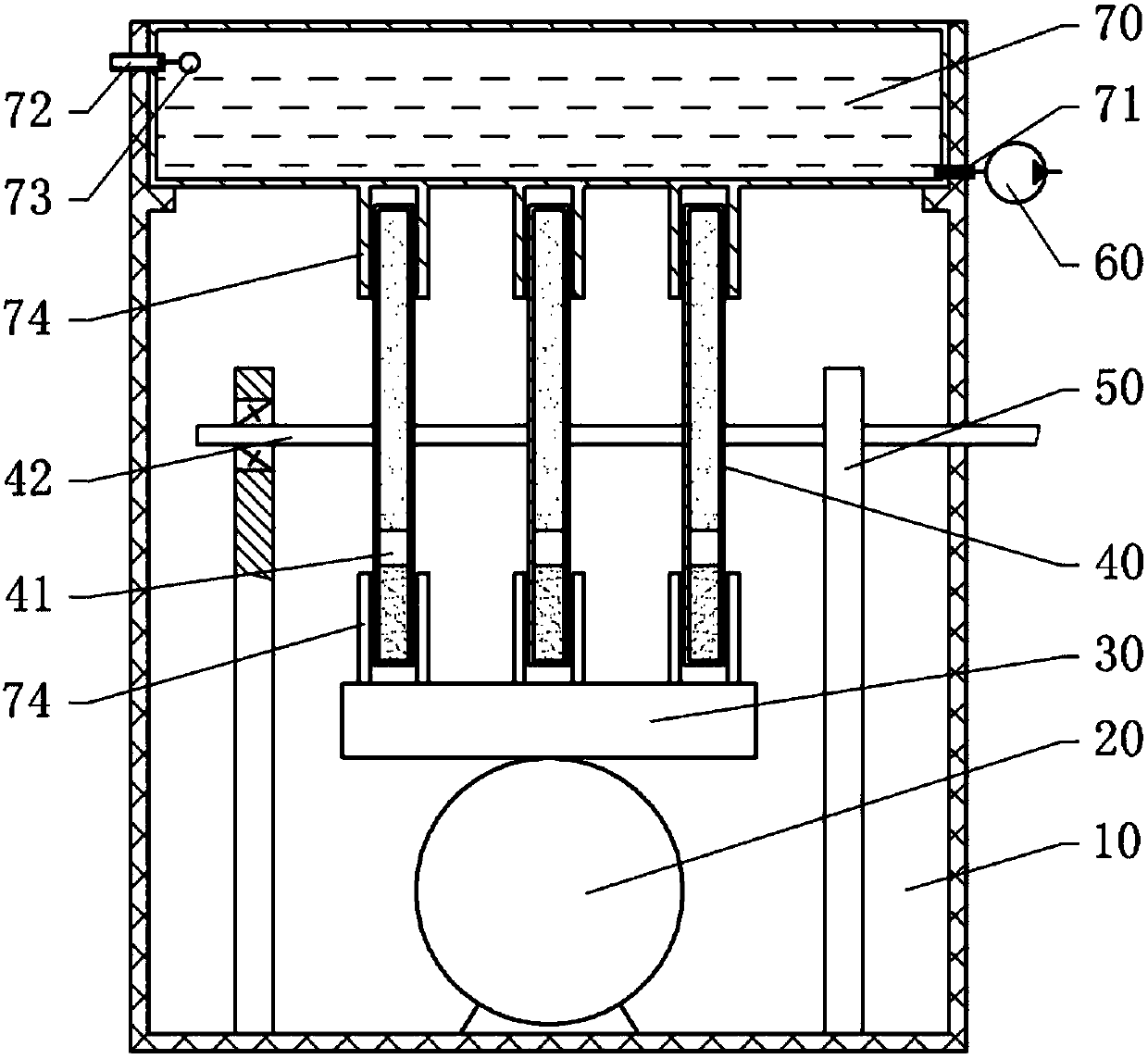
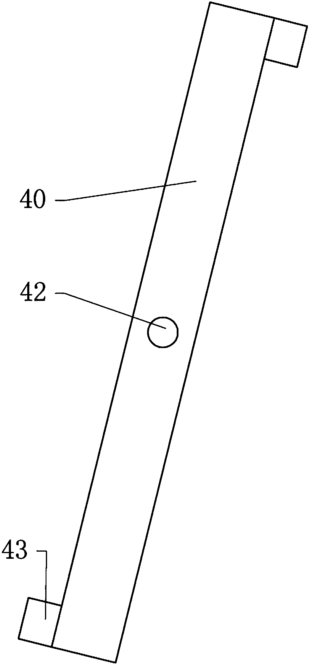
[0027] Such as figure 1 , figure 2 As shown, the energy storage device for reuse of waste heat from an air compressor includes an air compressor room 10 , an air compressor 20 is located in the air compressor room 10 , and a cooler 30 is connected to the air compressor 20 . The top of the air compressor room 10 is provided with a heat absorbing tank 70 and a water pump 60 , and the air compressor room 10 is provided with a heat energy conversion mechanism. The thermal energy conversion mechanism includes a bracket 50 fixed in the air compressor room 10 , a cylinder 40 mounted on the bracket 50 , and a piston 41 inside the cylinder 40 that can slide along the length of the cylinder 40 . The middle part of the cylinder body 40 is fixed with a rotating shaft 42, and the rotating shaft 42 is connected with the support 50 through a one-way bearing so that the cylinder body 40 can only rotate in one direction; The force on the end changes, so that the cylinder 40 will constantly ...

Embodiment 2

[0035] The difference between Embodiment 2 and Embodiment 1 is that in Embodiment 2, the impeller of the water pump is not connected to the rotating shaft of the cylinder body, but the water pump is driven through the electric connection between the generator and the water pump. Faster, the greater the current generated by the engine, the greater the speed of the water pump.


PUM

PropertyMeasurementUnit
Boiling pointaaaaaaaaaa

Abstract

The invention discloses an energy storage device for air compressor waste heat reuse and relates to an air compressor technology. The energy storage device mainly comprises an air compressor room formounting an air compressor, and the air compressor room is internally provided with a cooling device connected with the air compressor. A hot water absorbing tank and a water pump are arranged at thetop of the air compressor room, and the air compressor room is internally provided with a heat energy converting mechanism which comprises a support, a cylinder body arranged on the support, and a piston arranged in the cylinder body and capable of sliding. A rotary shaft is fixed to the middle of the cylinder body and rotatably connected with the support, and the interior of the cylinder body isdivided into a first cavity body and a second cavity body through the piston. The first cavity body and the second cavity body are internally provided with expanding agents correspondingly, and the expanding agents are liquid which achieves thermal expansion. A water inlet is formed in the upper portion of the hot water absorbing tank, and a water outlet is formed in the bottom of the hot water absorbing tank. The water outlet is connected with the water pump, and the cylinder body drives the water pump to operate when rotating along the rotary shaft. Waste heat generated by the air compressoris absorbed and stored through the hot water absorbing tank, and the hot water absorbing tank can serve as a water source for washing of workers in a plant area.

Description

technical field [0001] The invention relates to air compressor technology, in particular to an energy storage device used for recycling waste heat of an air compressor. Background technique [0002] An air compressor is a device used to compress gas. Air compressors are similar in construction to water pumps. Most air compressors are reciprocating piston, rotary vane or rotary screw. [0003] Air compressors can be widely used in mining, machinery manufacturing, construction, textile, petrochemical and other places that need to compress gas. The existing air compressor system mainly includes an air compressor, an oil-air separator and an oil cooler. During operation, the circulating cooling lubricating oil in the air compressor enters the oil cooler after passing through the oil-air separator, and is cooled by the oil cooler. Then it is recycled back into the air compressor. During the entire operation of the air compressor, about 90% of the input electric energy is conve...

Claims


Application Information

Patent Timeline
IPC IPC(8): F04B39/06F01B23/10F04B17/03
CPCF01B23/10F04B17/03F04B39/06
Inventor 唐辉
Owner 广东温博节能环保科技有限公司
Why Eureka
Try Eureka