Silver sol sintering oven for LED lamps

A technology of LED lamps and ovens, applied in the direction of furnace control devices, charge processing types, lighting and heating equipment, etc., can solve problems such as inconsistent curing time, prolonging sintering time, and different heating of dispensing, achieving good preheating effect and reducing Sintering time, easy debugging effect

Inactive Publication Date: 2018-03-30
SICHUAN ZHONGYONG PHARMA CO LTD
View PDF0 Cites 2 Cited by
  • Summary
  • Abstract
  • Description
  • Claims
  • Application Information

AI Technical Summary

Problems solved by technology

[0005] The purpose of the present invention is: to solve the problem of using more than one sintering port to sinter the silver glue on the led bracket during sintering, the sintering efficiency is slow, and the dispensing of glue in different positions is heated differently, resulting in inconsistent curing time and prolonged For the problem of sintering time, the present invention provides a silver glue sintering oven for LED lamps

Method used


Image

  • Silver sol sintering oven for LED lamps
  • Silver sol sintering oven for LED lamps
  • Silver sol sintering oven for LED lamps

Examples


Embodiment 1

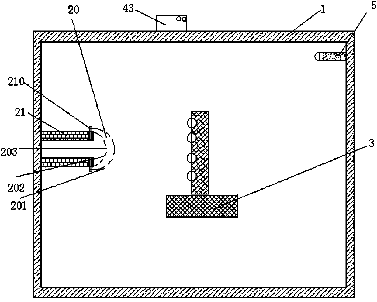
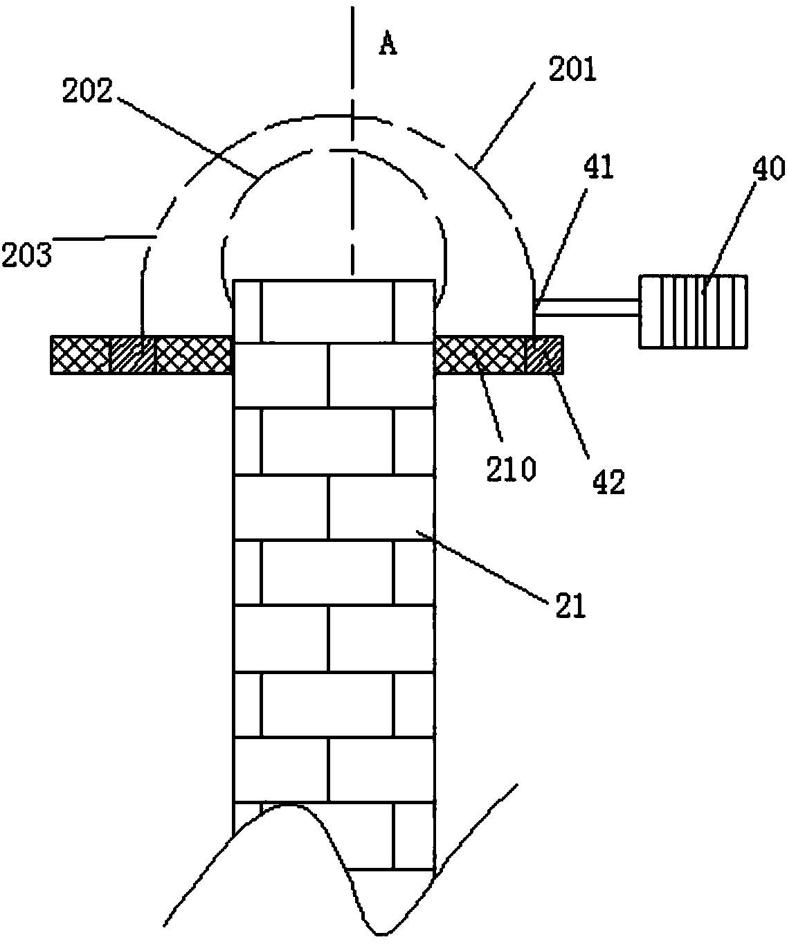
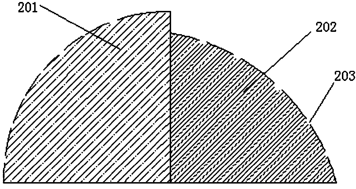
[0023] Such as Figure 1-3 As shown, a silver glue sintering oven for LED lights includes a sintering oven 1, a sintering port 2, and a limiting slot 3 matched with the sintering port 2. The sintering port 2, and the limiting slot 3 are arranged inside the sintering oven 1, and The port 2 includes a sintering mouthpiece 20, a sintering support rod 21, and a support rod 210 fixed to the sintering support rod 21. The sintering mouthpiece 20 includes a first sintering mouthpiece 201 and a second sintering mouthpiece 202. The first sintering mouthpiece 201 rotates around the support rod 210, The rotating mechanism includes a motor 40, a connecting rod 41, a bearing 42 and a thermostat 43. The output shaft of the motor 40 is connected to the connecting rod 41. One end of the connecting rod 41 is connected to the bearing 42, and the other end of the connecting rod 41 is fixed to the first sintering mouth 201 The bearing 42 is fixed on the support rod 210, the thermostat 43 is connect...

Embodiment 2

[0027] Further optimized on the basis of the silver glue sintering oven for LED lamps described in Embodiment 1, the limiting groove 3 is slidingly connected to the bottom of the junction oven 1. When the curing starts, in order to better preheat the LED lamp, the first sintering mouthpiece 201 is rotated on the second sintering mouthpiece 202, and the small sintering mouth 203 on the second sintering mouth 202 is covered, and the heat is removed from the sintering mouthpiece. The remaining part of 20 flows out, and the limit slot 3 moves on the oven 1 to make up for the uneven heat dissipation of the sintering mouth 20, which makes the LED lamp part on the limit slot 3 not heated.

Embodiment 3

[0029] Based on the silver glue sintering oven of the LED lamp described in embodiment 1 or 2, the rubber can play a buffering role when the LED lamp is placed on the limit slot 3 to prevent the position of the silver glue from moving when placed.


PUM


Abstract

The invention discloses a silver sol sintering oven for LED lamps. A sintering mouth comprises a sintering mouth head, a sintering supporting rod and a supporting rod fixed to the sintering supportingrod. The sintering mouth head comprises a first sintering mouth head body and a second sintering mouth head body, the first sintering mouth head body rotates around the supporting rod, the second sintering mouth head body is fixed to the sintering supporting rod, the second sintering mouth head body and the first sintering mouth head body are both semispherical, the radius value of the second sintering mouth head body is smaller than that of the first sintering mouth head body, the second sintering mouth head body and the first sintering mouth head body are provided with a plurality of smallsintering mouths, the positions of the small sintering mouths correspond to dispensing positions, and the distances between the small sintering mouths and the corresponding dispensing positions are equal. A limiting tank is in sliding connection with the bottom of a sintering oven body and can move. Meanwhile, the first sintering mouth head body moves, the limiting tank is matched with the first sintering mouth head body, and thus a better preheating effect on LED lamps is achieved, and the situation that silver sol is suddenly heated and consequently the later curing effect is affected is prevented.

Description

Technical field [0001] The invention relates to the technical field of LED lamp preparation, in particular to a silver glue sintering oven for LED lamps. Background technique [0002] Traditional lighting is usually realized by using incandescent lamps. Incandescent lamps use the heat generated when the filament passes the current through the filament, so that the temperature of the filament reaches the incandescent state above 2000 degrees Celsius, so that the filament emits light for lighting. In this process, the incandescent lamp It takes more heat to emit light, which is a waste of energy. In this context, people use diodes to make LED energy-saving lamps, and use the diodes to directly convert electrical energy into light to achieve lighting, reducing the energy consumed when lighting the bulb, so as to achieve the purpose of energy saving and environmental protection. [0003] In the LED lamp packaging process, it connects the outer lead to the electrode of the LED chip, pr...

Claims


Application Information

Patent Timeline
Patent Type & Authority Applications(China)
IPC IPC(8): F27B17/00F27D19/00F27D21/02G05D23/24H01L33/48
CPCF27B17/0025F27D19/00F27D21/02F27D2019/0028F27M2003/04G05D23/24H01L33/48
Inventor 刘金成刘浩云蔡帮明秦会
Owner SICHUAN ZHONGYONG PHARMA CO LTD
Why Eureka
Try Eureka