
Convenient PXIe module debugging tool

A technology for module debugging and tooling, applied in the direction of the casing of the measuring device, can solve the problems of low test efficiency, large test error, circuit short circuit, etc., and achieve the effect of speeding up the development progress, shortening the debugging time, and prolonging the service life.

Inactive Publication Date: 2018-03-30
THE 41ST INST OF CHINA ELECTRONICS TECH GRP
View PDF5 Cites 2 Cited by
  • Summary
  • Abstract
  • Description
  • Claims
  • Application Information

AI Technical Summary

Problems solved by technology

[0003] Directly insert the PXIe module to be debugged into the corresponding slot in the PXIe chassis for debugging without using the debugging tool. The disadvantage is that it is difficult to determine the position of the test point. When the circuit board needs to be tested, there are a lot of test point data. It is very inconvenient to insert the test leads into the narrow space in the chassis every time. The test efficiency is low and the test error is large, which seriously restricts the debugging progress of the PXIe module.

Method used


Image

  • Convenient PXIe module debugging tool
  • Convenient PXIe module debugging tool
  • Convenient PXIe module debugging tool

Examples


Embodiment Construction

[0016] The present invention will be further described below in conjunction with the accompanying drawings and specific embodiments.

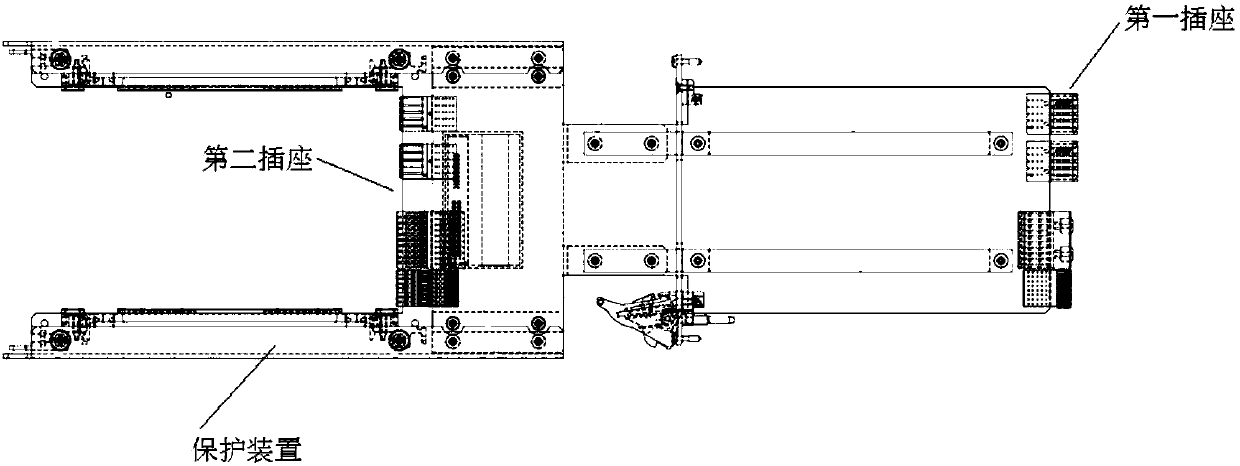
[0017] The structure diagram of the PXIe module debugging tooling of the present invention is as follows figure 1 shown. It includes: a tooling board, one end of the tooling board is provided with a first socket that can be connected to the socket on the backplane of the PXIe chassis, and the other end of the tooling board is provided with a second socket that can be connected to the PXIe module to be debugged.

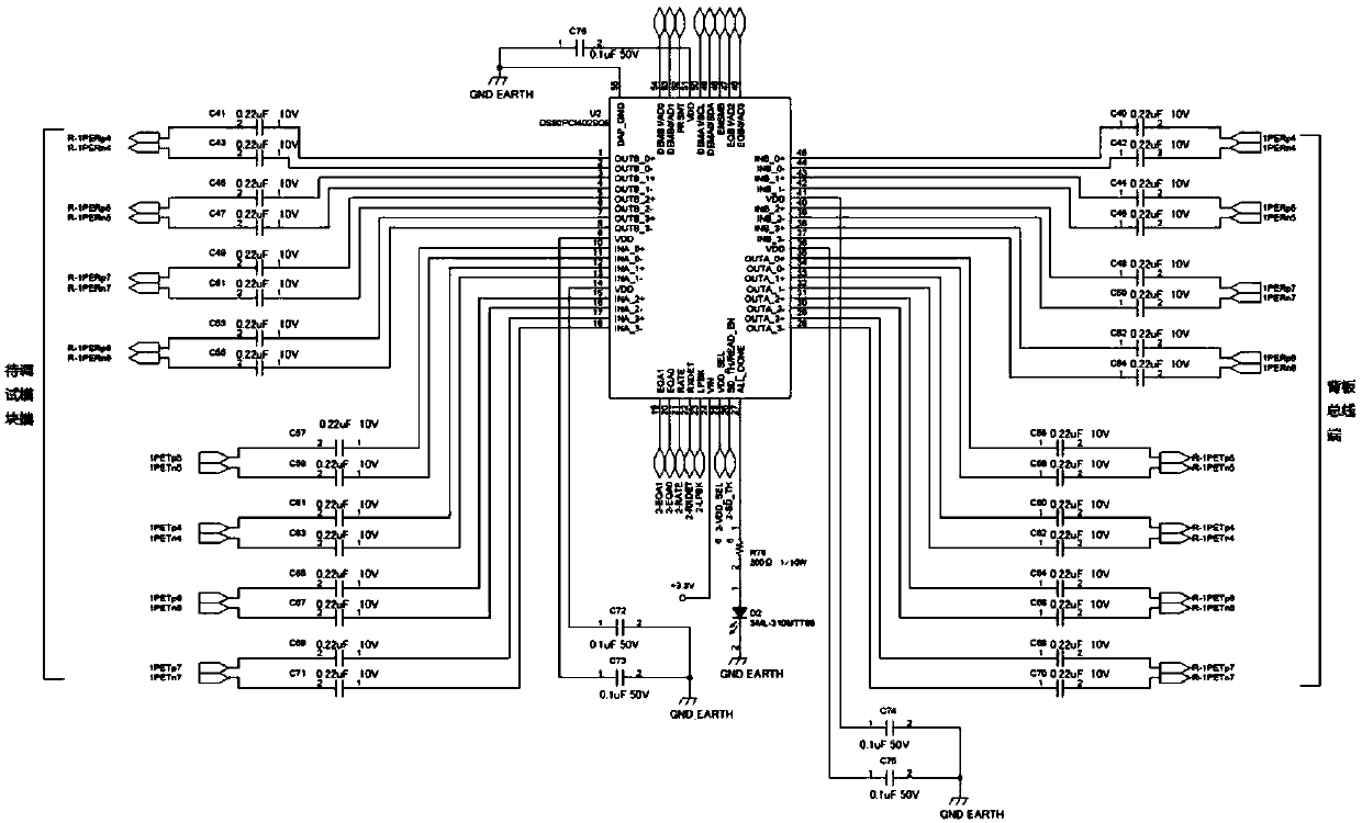
[0018] Through the first socket and the PXIe chassis backplane socket, the PXIe signal is led out one by one. The DS80PCI402 integrated circuit is designed on the tooling board to control the attenuation of the PXIe high-speed differential pair signal, which can ensure the high-speed differential pair signal. No loss, DS80PCI402 integrated circuit signal connection schematic diagram is as follows figure 2 shown.

[0019] As an impl...


PUM


Abstract

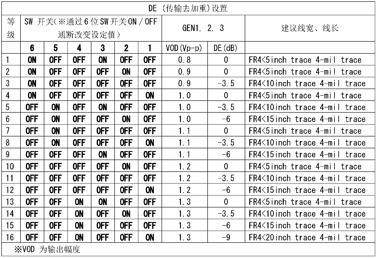
The invention discloses a convenient PXIe module debugging tool comprising a tool board card. One end of the tool board card is provided with first sockets capable of being docked with a PXIe case backboard socket. The other end of the tool board card is provided with second sockets capable of being docked with a PXIe module. The first sockets and the second sockets are connected in a one-to-one correspondence way so as to lead out all the signals of the case backboard. The beneficial effects of the convenient PXIe module debugging tool are that all the signals of the case backboard are led out through the tool board card without difference, the attenuation of the signals is controlled through the integrated circuit, the line width and the line length of the high-speed difference signals between the case backboard and the PXIe module are matched by the switch, the service life is prolonged by using the steel protection structure design, then the debugged PXIe module is inserted in thetool socket to be debugged and the signal of each position of the PXIe module can be clearly, rapidly, conveniently and accurately tested through the test instrument so that the module debugging timecan be shortened, the debugging efficiency can be enhanced and the development progress can be accelerated.

Description

technical field [0001] The invention relates to a convenient PXIe module debugging tool. Background technique [0002] At present, the PXIe system composed of PXIe modules has become the standard platform in the field of test and measurement due to its advantages in execution speed, test accuracy, and bandwidth performance. However, to build more types of PXIe systems, it is necessary to develop more types of PXIe module. At present, when debugging PXIe modules, because there is no ready-made debugging tool, the PXIe module to be debugged can only be directly inserted into the corresponding slot in the PXIe chassis, and then the module is powered on. If you want to test a test point signal in the module, you need to use Hold the test leads of multimeters, oscilloscopes and other test instruments and extend them into the chassis, touch the probes of the test leads to the test points of the PXIe module circuit board, and read the voltage, waveform and other data of test instr...

Claims


Application Information

Patent Timeline
Patent Type & Authority Applications(China)
IPC IPC(8): G01R1/04
Inventor 刘明军李智唐建立郭荣斌杨成
Owner THE 41ST INST OF CHINA ELECTRONICS TECH GRP
Learn More