Through-flow device for large transformer

A technology for transformers and transformer bushings, applied in the field of transformers, can solve the problems of inaccurate results, insufficient measurement accuracy, and small secondary side current.

Inactive Publication Date: 2018-03-30
SHANDONG ELECTRIC POWER TRANSMISSION & SUBSTATION ENG CO
View PDF7 Cites 3 Cited by
  • Summary
  • Abstract
  • Description
  • Claims
  • Application Information

AI Technical Summary

Problems solved by technology

[0005] In order to overcome the problems of the secondary side current of the current transformer CT being too small, the result of the current test being inaccurate and the measurement accuracy not high enough in the current test in the related art, this application provides a large-scale transformer current-through device

Method used


Image

  • Through-flow device for large transformer
  • Through-flow device for large transformer
  • Through-flow device for large transformer

Examples


Embodiment 1

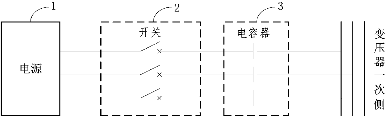
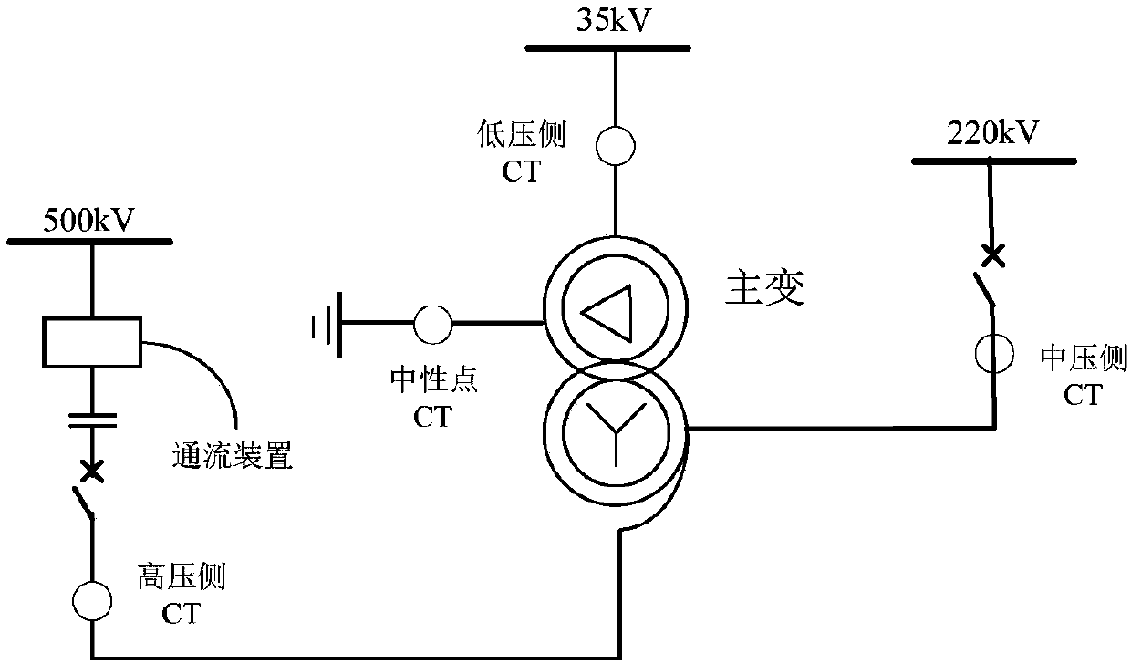
[0036] The large-scale transformer current-through device in the embodiment of the present application is used for a transformer of 500kV and above, and a current transformer CT is arranged inside the transformer bushing, and the primary side of the current transformer CT is arranged in the primary side circuit of the transformer. see figure 1 , figure 1 It is a schematic structural diagram of a large-scale transformer flow-through device provided in the embodiment of the present application. figure 1 It can be seen that the large-scale transformer current-through device mainly includes a power supply 1, a switch 2, and a capacitor 3 connected in series in sequence. The capacitor 3 is connected in series with the primary side of the transformer, and the capacitor 3 is used to form series resonance in the series circuit.

[0037] Furthermore, since the conductive rod on the primary side of the transformer runs through the inside of the transformer bushing and is led out of the...

Embodiment 2

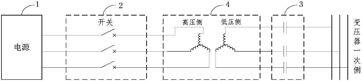
[0143] The large-scale transformer current-through device in the embodiment of the present application is used for a transformer of 500kV and above, and a current transformer CT is arranged inside the transformer bushing, and the primary side of the current transformer CT is arranged in the primary side circuit of the transformer. see image 3 , image 3 It is a schematic structural diagram of another large-scale transformer flow-through device provided in the embodiment of the present application. Depend on image 3 It can be seen that the large-scale transformer current-through device mainly includes a power supply 1 , a switch 2 , an isolation transformer 4 and a capacitor 3 which are sequentially connected in series. The high voltage side of the isolation transformer 4 is connected to the switch 2 , and the low voltage side of the isolation transformer 4 is connected to the capacitor 3 in series. The capacitor 3 is connected in series with the primary side of the transf...

Embodiment 3

[0250] The large-scale transformer current-through device in the embodiment of the present application is used for a transformer of 500kV and above, and a current transformer CT is arranged inside the transformer bushing, and the primary side of the current transformer CT is arranged in the primary side circuit of the transformer. see Figure 4 , Figure 4 It is a schematic structural diagram of another large-scale transformer flow-through device provided in the embodiment of the present application. Depend on Figure 4 It can be seen that the large-scale transformer flow-through device mainly includes a power supply 1, a switch 2, an isolation transformer 4 and a capacitor 3 connected in series in sequence, wherein a voltage regulating device 5 is provided between the power supply 1 and the isolation transformer 4, and the voltage regulating device 5 is used for Adjust the size of the primary side current of the transformer, thereby controlling the size of the secondary sid...


PUM

PropertyMeasurementUnit
Capacitanceaaaaaaaaaa

Abstract

The application relates to a through-flow device for a large transformer, and is used for a transformer of 500 kV and above. The device includes a power supply, a switch and a capacitor sequentially connected in series, and the capacitor and the primary side of the transformer are connected in series to form series resonance in a series circuit. According to the through-flow device for the large transformer, the capacitor is connected in a primary side loop of the transformer in series, total impedance in the circuit can be reduced, a function of reactive compensation or power compensation isrealized, thus primary currents in the circuit can be greatly improved, and since primary currents increase, secondary side currents of a current transformer (CT) in the circuit also increase, therebyimproving accuracy and precision of current measurement.

Description

technical field [0001] The present application relates to the technical field of transformers, in particular to a large-scale transformer flow-through device. Background technique [0002] In the construction and commissioning of the substation project, in order to ensure the correctness of the transformer connection mode and the CT (Current Transformer, current transformer) connection polarity, it is necessary to conduct a current test on the transformer, that is, a simulated power transmission test. For large transformers above 500kV, there are generally three flow-through test methods: high-voltage side-medium-voltage side flow-through, medium-voltage side-low-voltage side flow-through, and high-voltage side-low-voltage side flow-through. Generally, high-pressure side-medium-pressure side flow and medium-pressure side-low pressure side flow are used. Take the high-voltage side-medium voltage side flow test as an example. The so-called one-time flow test is to apply three...

Claims


Application Information

Patent Timeline
IPC IPC(8): G01R31/02G01R31/04G01R31/06
CPCG01R31/62G01R31/66G01R31/72
Inventor 陶宇吴遨郝克敬涛王鸿志夏栩宋帅李雪郇蕊梦郑艳彬王德丽贺景俞田菲菲李光瑞张聪刘海艳林永祥徐云珂
Owner SHANDONG ELECTRIC POWER TRANSMISSION & SUBSTATION ENG CO
Why Eureka
Try Eureka