
Calibration method and device

A calibration method and variance technology, applied in radio wave measurement systems, instruments, etc., can solve the problems of inconsistency and large errors of ranging machines, and achieve the effect of improving generalization ability, reliable results, and improving measurement accuracy.

Active Publication Date: 2018-03-30
SHEN ZHEN 3IROBOTICS CO LTD
View PDF7 Cites 17 Cited by
  • Summary
  • Abstract
  • Description
  • Claims
  • Application Information

AI Technical Summary

Problems solved by technology

[0004] However, in the laser triangulation ranging method, although the change in the distance is approximately proportional to the change in the displacement of the laser spot on the CMOS, the displacement is easily affected by the external environment and the performance of the optical system, material, and components. The error is relatively large, and there is inconsistency in the error of each ranging machine, so it is necessary to calibrate the laser radar used

Method used


Image

  • Calibration method and device
  • Calibration method and device
  • Calibration method and device

Examples


no. 1 example

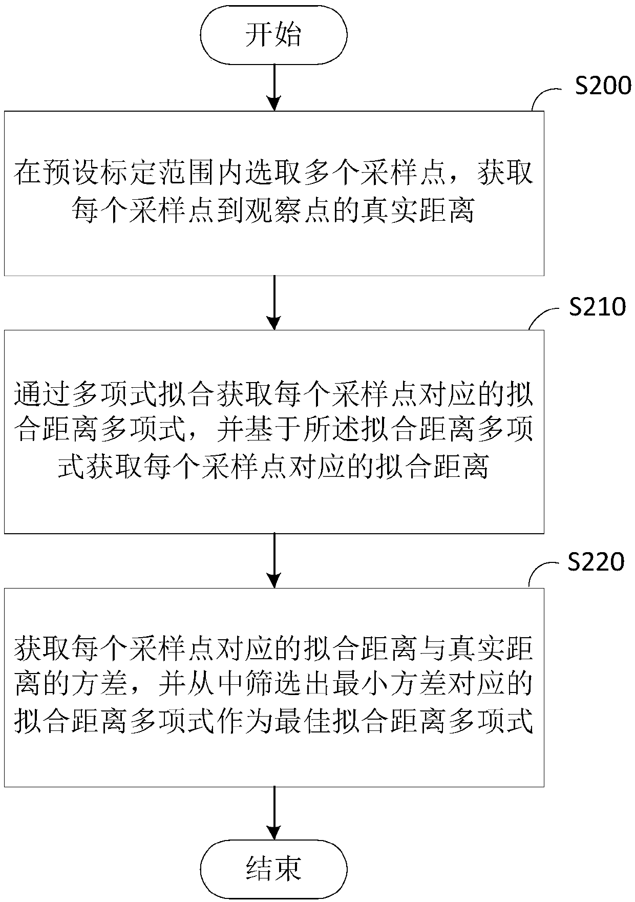
[0031] Please refer to figure 2 , this embodiment provides a calibration method applied to a calibration device, the method comprising:

[0032]Step S200: Select a plurality of sampling points within the preset calibration range, and obtain the real distance from each sampling point to the observation point;

[0033] In this embodiment, the calibration method can be applied to devices such as laser radars or common laser range finders, and in particular, can also be applied to laser range finders installed on mobile robots. The preset calibration range can be the detection range set before calibration, and an appropriate calibration range can be selected according to the performance of the specific calibration environment and the measurable range of the distance measuring device (eliminate the measurement error caused by the environment as much as possible. ), and the preset calibration range can be determined in various forms. For example, by setting up the slide table, th...

no. 2 example

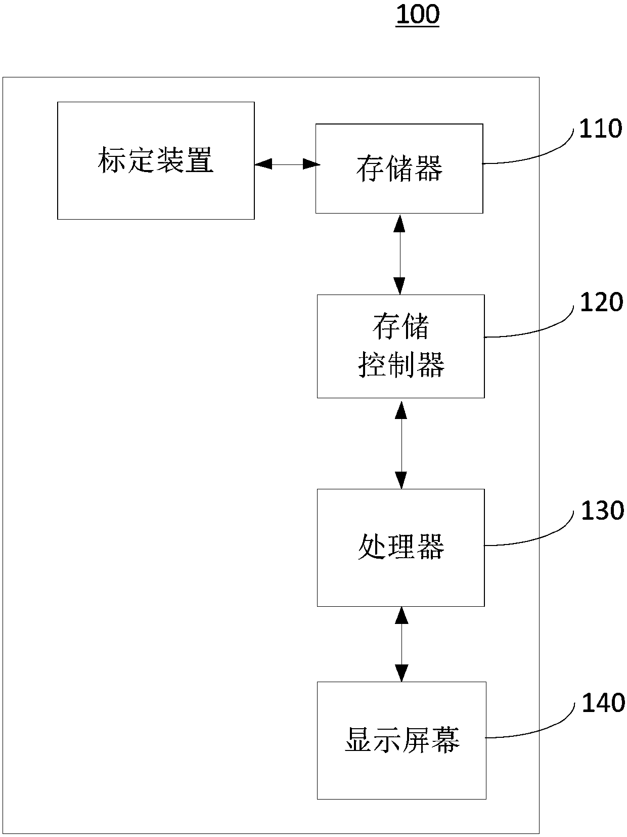
[0080] Please refer to Figure 8 , this embodiment provides a calibration device 800, which includes:

[0081] The sampling module 810 is used to select a plurality of sampling points within the preset calibration range to obtain the true distance from each sampling point to the observation point;

[0082] A fitting module 820, configured to obtain a fitting distance polynomial corresponding to each sampling point through polynomial fitting, and obtain a fitting distance corresponding to each sampling point based on the fitting distance polynomial;

[0083] The screening module 830 is configured to obtain the variance of the fitting distance corresponding to each sampling point and the real distance, and select the fitting distance polynomial corresponding to the minimum variance as the best fitting distance polynomial.

[0084] Please refer to Figure 9 , in this embodiment, further, the fitting module 820 may also include the following units:

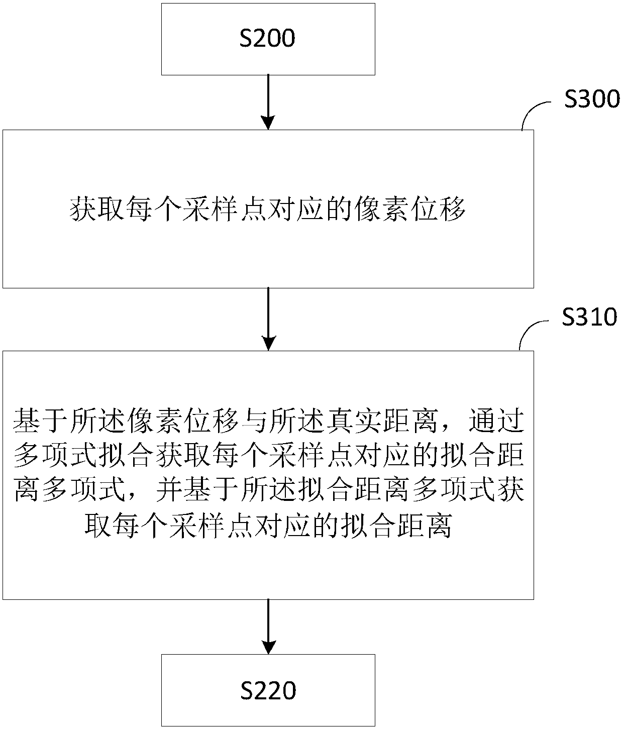
[0085] A pixel unit 821, co...


PUM


Abstract

The invention provides a calibration method and device, and relates to the field of laser ranging. The calibration method comprises the steps of selecting a plurality of sampling points within a preset calibration range, and acquiring the actual distance between each sampling point and an observation point; acquiring a fitting distance polynomial corresponding to each sampling point through polynomial fitting, and acquiring the fitting distance corresponding to each sampling point based on the fitting distance polynomial; and acquiring the variance between the fitting distance corresponding toeach sampling point and the actual distance; and screening out the fitting distance polynomial corresponding to the minimum variance to serve as the optimal fitting distance polynomial. According tothe method and device provided by the invention, a plurality of fitting polynomials which are approximate to the actual value are created through polynomial fitting, then the most accurate function isscreened out through comparing the variance, targeted calibration can be provided for ranging radar with different performance parameters, the operation is convenient, the result is reliable, and themeasurement accuracy of laser triangulation ranging can be effectively improved.

Description

technical field [0001] The invention relates to the field of laser ranging, in particular to a calibration method and device. Background technique [0002] Laser Distance Measuring (Laser Distance Measuring) uses a laser as a light source for distance measurement. The laser rangefinder is an instrument that uses laser to accurately measure the distance of the target. According to the way the laser works, it is divided into continuous laser and pulsed laser. Gas lasers such as helium-neon, argon ions, and krypton-cadmium work in a continuous output state and are used for phase laser ranging; double heterogeneous gallium arsenide semiconductor lasers are used for infrared ranging; solid-state lasers such as ruby ​​and neodymium glass are used for Pulsed laser ranging. Compared with the photoelectric range finder, the laser range finder can not only work day and night, but also improve the distance measurement accuracy and significantly reduce the weight and power consumpti...

Claims


Application Information

Patent Timeline
IPC IPC(8): G01S7/497
CPCG01S7/497
Inventor 李崇国杨勇宫海涛万军雷
Owner SHEN ZHEN 3IROBOTICS CO LTD
Learn More