Universal clamp for drilling crankshaft oil hole by vertical type machining center

A vertical machining center and crankshaft oil hole technology, which is applied in the direction of manufacturing tools, metal processing equipment, metal processing machinery parts, etc., can solve the problems of high manufacturing cost, low processing precision, low production efficiency, etc., and achieve a simple and compact overall structure , Improve machining accuracy and save equipment investment

Pending Publication Date: 2018-04-03
内江金鸿曲轴有限公司
View PDF0 Cites 0 Cited by
  • Summary
  • Abstract
  • Description
  • Claims
  • Application Information

AI Technical Summary

Problems solved by technology

[0002] At present, there are mainly three ways to process the crankshaft hole in the domestic crankshaft production line. One is to process the crankshaft hole through the radial drilling machine combined with special tooling. Each type of crankshaft requires a special tooling for the support, so the production efficiency is low and the labor intensity of the operator is relatively high
[0003] Another way is to use simple special equipment for processing. Similar to the above method, this processing method also has the disadvantage of poor versatility; and the processing accuracy of the product is low, and it is difficult to replace the crankshaft variety.
[0004] Another method is to use a five-axis horizontal machining center for processing, but the disadvantage of this method is that the investment in equipment is large, and the purchase price of each machine tool is more than one million yuan.
Ordinary vertical machining centers lack universal fixtures that can process crankshafts of different models, different angles, spindle diameters, and connecting rod diameters. There are poor versatility among various fixtures, high manufacturing costs, long production cycles, and low efficiency. and other shortcomings

Method used


Image

  • Universal clamp for drilling crankshaft oil hole by vertical type machining center
  • Universal clamp for drilling crankshaft oil hole by vertical type machining center
  • Universal clamp for drilling crankshaft oil hole by vertical type machining center

Examples


Embodiment Construction

[0031] The present invention will be further described below in conjunction with accompanying drawing:

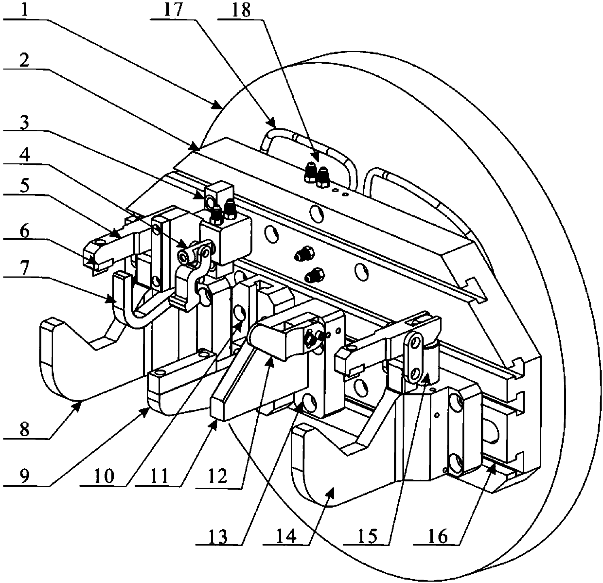
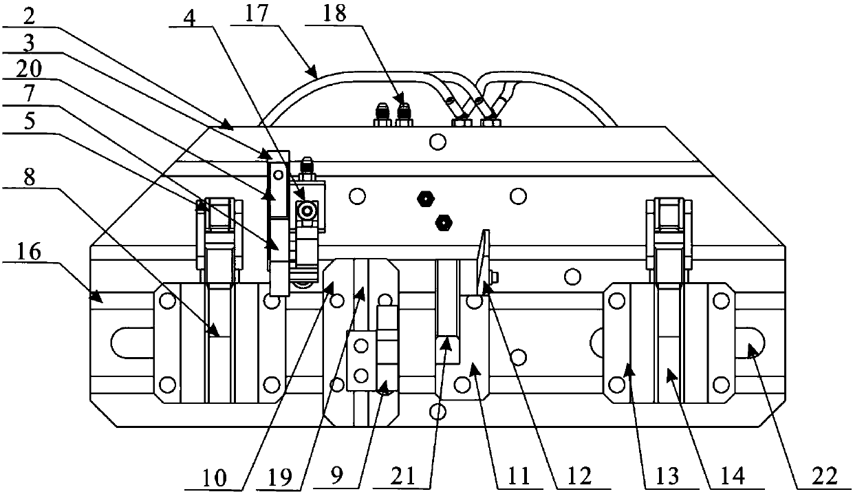
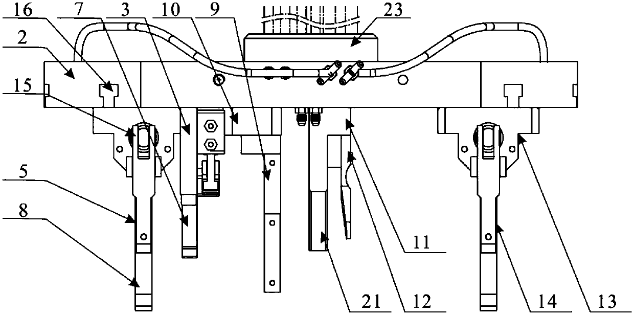
[0032] Such as Figure 1 to Figure 4 As shown in , it is a schematic structural diagram of a universal fixture for drilling crankshaft oil holes in a vertical machining center.

[0033] The universal clamp for crankshaft oil hole drilling of the vertical machining center of the present invention includes a turntable 2 and a fixed seat, the turntable 2 is a polygonal structure, the rear end of the turntable 2 is provided with a turntable 23, and a high-pressure spring is installed on the turntable 23, and the turntable 2 passes through the high-pressure spring It is connected with the CNC turntable 1 of the vertical machining center; there are at least two T-shaped slots 16 arranged in parallel on the turntable 2, generally there are four T-shaped slots 16, and the position between the lower two T-shaped slots 16 is close to the left and right edges Two cavities 22 are arra...


PUM


Abstract

The invention discloses a universal clamp for drilling a crankshaft oil hole by a vertical type machining center. The universal clamp comprises a turntable and a fixed seat, wherein at least two T-shaped slots are formed in the turntable in parallel; the fixed seat is mounted on the turntable through the T-shaped slots; the fixed seat comprises a left side V-shaped supporting seat, a locating hookfixing seat, a radial locating seat, an axial locating seat and a right side V-shaped supporting seat; a hydraulic oil cylinder is arranged inside the fixed seat; the hydraulic oil cylinder is connected with oil cylinder screw piles; and the oil cylinder screw piles are connected with a high-pressure oil pipe. The universal clamp can clamp crankshafts in different sizes and different lengths, andhas the advantages of high universality, low manufacturing cost, compact structure, improvement of the production efficiency and the like.

Description

technical field [0001] The invention belongs to the technical field of mechanical devices and transportation, and in particular relates to a general fixture for drilling crankshaft oil holes of a vertical machining center. Background technique [0002] At present, there are mainly three ways to process the crankshaft hole in the domestic crankshaft production line. One is to process the crankshaft hole through the radial drilling machine combined with special tooling. Each type of crankshaft requires a special tooling for the support, so the production efficiency is low and the labor intensity of the operator is relatively high. [0003] Another method is to use simple special equipment for processing. Similar to the above method, this processing method also has the disadvantage of poor versatility; and the processing accuracy of the product is low, and it is difficult to replace the crankshaft type. [0004] Another method is to use a five-axis horizontal machining center ...

Claims


Application Information

Patent Timeline
IPC IPC(8): B23Q3/08
CPCB23Q3/082B23Q2703/04
Inventor 李启伟陆涛
Owner 内江金鸿曲轴有限公司
Why Eureka
Try Eureka