
Dilution device for straw papermaking slurry

A technology of dilution device and slurry, which is used in mixers with rotary stirring devices, transportation and packaging, pre-processing of mixed materials, etc., can solve the problems of reducing the efficiency of subsequent steps, difficult to meet the requirements of the conveying screw, and avoid product quality. very poor effect

Inactive Publication Date: 2018-04-06
JIANGYIN XINHAI ROAD CONSTR MATERIAL
View PDF0 Cites 6 Cited by
  • Summary
  • Abstract
  • Description
  • Claims
  • Application Information

AI Technical Summary

Problems solved by technology

[0003] In the above process steps, conveying the washed pulp to the subsequent steps requires the use of a conveying screw. However, because the pulp is seriously agglomerated after pulp washing, simply conveying the lumpy pulp will greatly reduce the efficiency of the subsequent steps. ; Therefore, for the particularity of straw production slurry, the traditional conveying screw is difficult to meet the requirements

Method used


Image

  • Dilution device for straw papermaking slurry

Examples


Embodiment 1

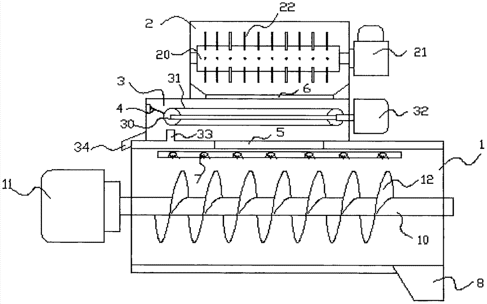
[0015] as attached figure 1 Shown: a dilution device for straw papermaking slurry, including a dilution tank 1, the top of the dilution tank 1 is provided with a feed port 5, and the bottom is provided with a discharge port 8, and the horizontal central axis in the dilution tank 1 is A rotating shaft 10 is installed, and one end of the rotating shaft 10 is provided with a first driving device 11, and the rotating shaft 10 is surrounded by a helical blade 12, and the upper part of the dilution tank 1 is provided with several water spray ports 7; 5, a feed tank body is installed above, and the feed tank body includes an upper crushing tank 2 and a lower filter tank 3, and a crushing roller 20 with crushing teeth 22 is arranged horizontally in the crushing tank 2, and the crushing tank 2 One end of the roller 22 is connected with a second driving device 21, and the bottom of the crushing tank 2 is provided with a discharge port 6 connected to the filter tank 3; the filter tank 3 ...

Embodiment 2

[0017] On the basis of Embodiment 1, a preferred embodiment of the present invention is that two belt rollers 30 distributed horizontally, a belt 31 around the two belt rollers 30 and a roller shaft connecting the belt rollers 30 are provided in the filter tank 3 Vibrating motor 32, described belt 31 is the belt that has mesh screen hole, all the other structures are identical with embodiment 1.

Embodiment 3

[0019] On the basis of Embodiment 2, the preferred embodiment of the present invention also includes that a scraper 4 is arranged on the side wall of the filter tank 3, and the blade of the scraper 4 is close to the surface above the roller shaft of the belt roller 30, and The bottom of the filter tank 3 directly below the belt roller 30 is provided with a protrusion 33, and the rest of the structure is exactly the same as that of Embodiment 2.


PUM


Abstract

The invention relates to a dilution device for straw papermaking slurry. The dilution device comprises a dilution trough, wherein a feeding hole is formed in the top of the dilution trough, a discharging hole is formed in the bottom of the dilution trough, a rotating shaft is mounted at a transverse middle axis in the dilution trough, first driving equipment is arranged at one end of the rotatingshaft, the rotating shaft is surrounded by spiral blades, and a plurality of water nozzles are formed in the upper part of the dilution trough; a feeding trough body is mounted on the feeding hole andcomprises an upper-layer crushing trough and a lower-layer filtering trough, a crushing roll with crushing teeth is transversely arranged in the crushing trough, one end of the crushing roll is connected to second driving equipment, and a discharging hole communicated with the filtering trough is formed in the bottom of the crushing trough; and the filtering trough is used for filtering crushed slurry in a screen net filtration manner. The dilution device can meet the requirements on the conveying of the straw papermaking slurry, the agglomeration of the slurry can be reduced, the dilution can be realized, and the dilution uniformity is high.

Description

technical field [0001] The invention relates to the technical field of papermaking equipment, in particular to a dilution device for straw papermaking slurry. Background technique [0002] Wood is generally used as the main raw material in the papermaking industry, but with the further deterioration of the environment, this process of using logs as raw materials is gradually being replaced. In order to meet the needs of the papermaking industry to the greatest extent, the use of fur , Cotton stalks, reeds, corn stalks, straw and other grasses as raw materials for pulping not only provide a new source of fiber for the paper industry, but also realize the utilization of waste, changing the original above-mentioned materials that can only be incinerated or recycled. In the case of Tiantian, the comprehensive utilization of resources has been realized, which has excellent social and economic benefits. In the process of processing raw materials, the above-mentioned raw materials...

Claims


Application Information

Patent Timeline
Patent Type & Authority Applications(China)
IPC IPC(8): B01F7/08B01F3/20B01F23/70
CPCB01F23/708B01F23/71B01F23/713B01F27/72B01F2101/47
Inventor 周永君
Owner JIANGYIN XINHAI ROAD CONSTR MATERIAL
Learn More