Rear brake device of vehicle

A brake device and rear wheel technology, applied to bicycle brakes, axle suspension devices, brake types, etc., can solve the problems of easily increasing the space for brake calipers and the number of accessories, and achieve the effect of reducing size

Inactive Publication Date: 2018-04-06
HONDA MOTOR CO LTD
View PDF5 Cites 2 Cited by
  • Summary
  • Abstract
  • Description
  • Claims
  • Application Information

AI Technical Summary

Problems solved by technology

[0004] However, in the structure described in Patent Document 1, since the support plate member for fixing the two brake calipers to the rocker arm is provided, there is a problem that the arrangement space of the brake calipers and the number of parts are likely to be increased.

Method used


Image

  • Rear brake device of vehicle
  • Rear brake device of vehicle
  • Rear brake device of vehicle

Examples


Embodiment Construction

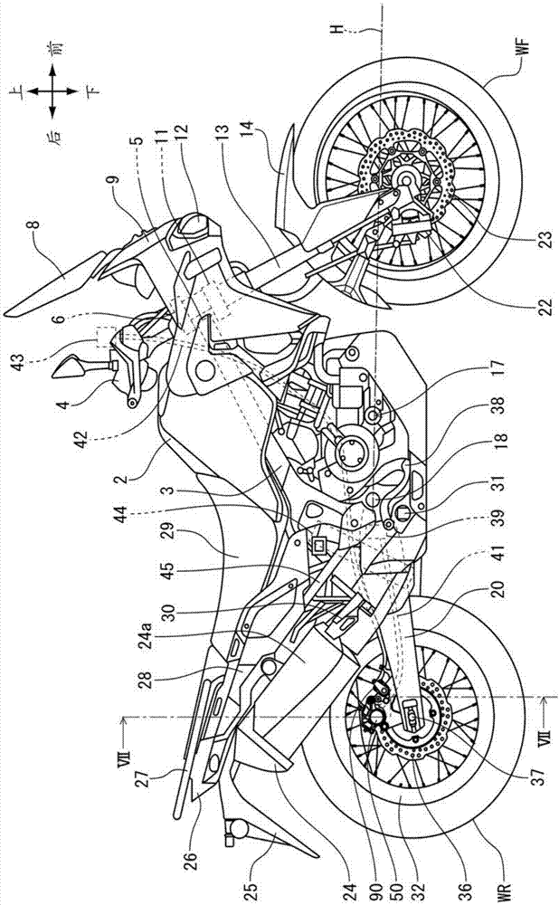
[0031] Hereinafter, preferred embodiments of the present invention will be described in detail with reference to the drawings. figure 1 It is a right side view of the motorcycle 1 to which the rear wheel braking device of the vehicle according to one embodiment of the present invention is applied. The motorcycle 1 is a dual-purpose saddle-riding type vehicle that travels while transmitting the driving force of the engine 17 as a power source to the rear wheels WR.

[0032]A head pipe 5 pivotally supporting a not-shown steering shaft is provided at a vehicle body front end portion of a vehicle body frame 3 constituting a vehicle body frame. A pair of left and right front forks 13 that rotatably pivotally support the front wheel WF are supported by a top beam 6 and a bottom beam 11 fixed to the steering shaft above and below the head pipe 5 . A steering handle 4 is fixed on the top of the top beam 6 . A front wheel braking device including a brake disc 23 and a brake caliper 2...


PUM


Abstract

A rear brake device of a vehicle is provided. A service brake caliper (50) and the parking brake caliper (hereinafter called P caliper) (90) are supported by a swing arm (20) rotatably supporting therear wheel (WR). The service brake caliper (50) and the P caliper (90) are configured to brake the brake disc (36). In the rear brake device of the vehicle, the service brake caliper (50) and the P caliper (90) are fixed to a stay member (40), the stay member (40) being supported by the swing arm (20). At least some of the service brake caliper (50) and the P caliper (90) are arranged in positionsforward of a vehicle body and upward of the vehicle body from an axle (37) of the rear wheel (WR). A first boss (54) and a third boss (93) are arranged on a straight line (L) passing through a centerpoint (O) of the axle (37).

Description

technical field [0001] The present invention relates to a rear wheel brake device for a vehicle, and more particularly to a rear wheel brake device for a vehicle having a parking brake caliper in addition to a normal brake caliper. Background technique [0002] Conventionally, there has been known a rear wheel brake device for a vehicle, which has a common brake caliper for generating a rear wheel braking force during running through the operation of a rear wheel brake operating member, and A parking brake caliper that operates to generate rear wheel braking force when parking. [0003] Patent Document 1 discloses a rear wheel brake device for a motorcycle, in which a normal brake caliper is arranged at a position behind the rear wheel axle with respect to a rocker arm that rotatably pivotally supports the rear wheel, and A parking brake caliper is located above the rear axle. [0004] However, in the structure described in Patent Document 1, since a support plate member i...

Claims


Application Information

Patent Timeline
Patent Type & Authority Applications(China)
IPC IPC(8): B62L1/02B62K25/20B62M7/02
CPCB62K25/20B62K2202/00B62L1/02B62M7/02B62K11/04B62K19/38B62K25/283B62L1/005F16D65/18F16D2055/0008F16D2055/0091F16D2121/04F16D2121/14F16D65/0075
Inventor 稻瀬耕介岩田正行后乡和彦
Owner HONDA MOTOR CO LTD
Why Eureka
Try Eureka