Double-winding drum type vehicle traction system for entertainment

A vehicle traction, reel-type technology, applied in the field of vehicle traction, can solve the problems of wire rope height difference, easy to cause safety hazard accidents, inflexible operation, etc., and achieve mechanization of the adjustment process, which is beneficial to long-term benefits and flexible and changeable operation Effect

Pending Publication Date: 2018-04-06
HUAQIANG FANGTE WUHU CULTURE TECH CO LTD
0 Cites 0 Cited by

AI-Extracted Technical Summary

Problems solved by technology

Generally, a conventional winch uses a drum to wind a steel wire rope, and the two ends of the steel wire rope are drawn out to pull the wire rope forward and backward respectively. This method makes the entire hoist device bulky and heavy, and it is difficult to move. The height difference increases the difficulty of connection between the wire rope and the traction vehic...

Abstract

The invention relates to a double-drum type vehicle traction system for entertainment, which includes a bottom plate, two steel wire rope winding mechanisms arranged symmetrically on the left and right, the steel wire rope winding mechanism includes a drum mechanism and an adjustment mechanism; the adjustment mechanism includes a moving seat, a roller , column, long plate, fixed column; the tops of the two long plates are jointly hinged with a transition plate, and the transition plate is connected with a hydraulic cylinder; the reel mechanism includes a reel, a small tapered friction wheel, and a wire rope; the reel is equipped with a drive shaft, The bottom of the transmission shaft is provided with a large tapered friction wheel, the large tapered friction wheel is connected with a motor, the motor is fixed with a support block, the support block is matched with a trapezoidal block, and the trapezoidal block is connected with a hydraulic cylinder. The present invention adopts the method of double drums, reduces the volume, reduces the mass and is easy to move, which is beneficial to the connection between the wire rope and the traction vehicle, has high stability, and can avoid safety accidents; realizes the adjustment of the distance between the wire ropes, and is suitable for use in different situations , the operation is flexible and changeable, and the adjustment process is simple.

Application Domain

Winding mechanisms

Technology Topic

Electric machineryTraction system +9

Image

  • Double-winding drum type vehicle traction system for entertainment
  • Double-winding drum type vehicle traction system for entertainment
  • Double-winding drum type vehicle traction system for entertainment

Examples

  • Experimental program(1)

Example Embodiment

[0022] In order to make the technical means, creative features, objectives and effects of the present invention easy to understand, the present invention will be further explained below.
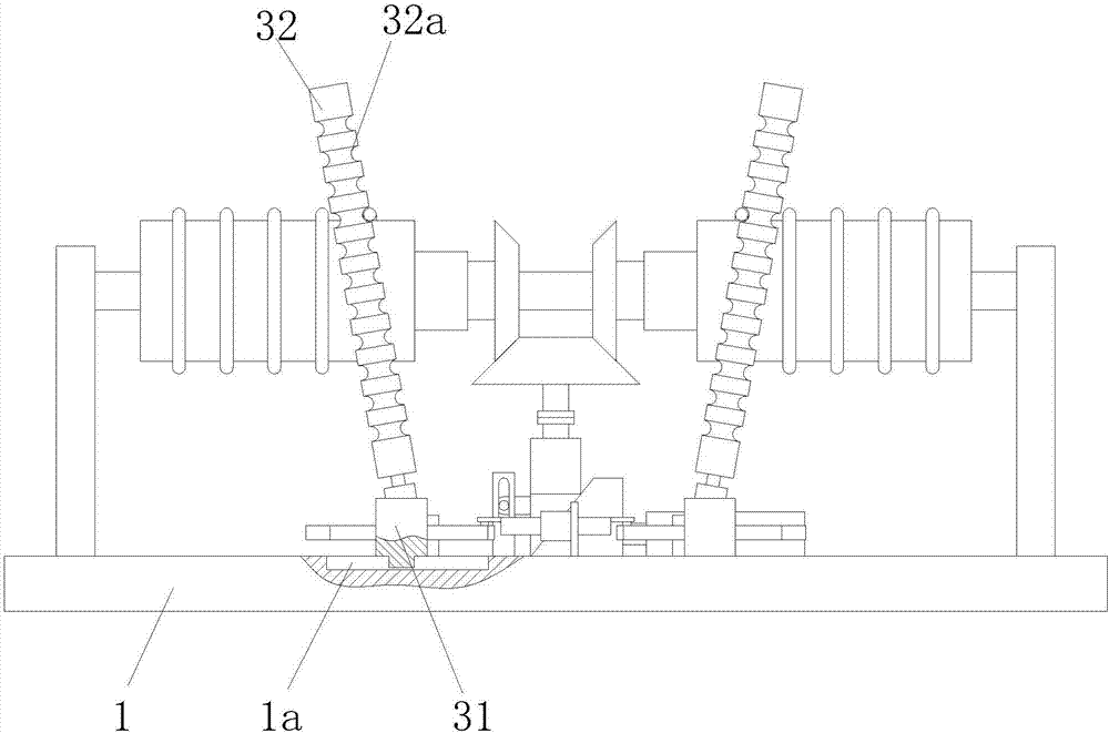
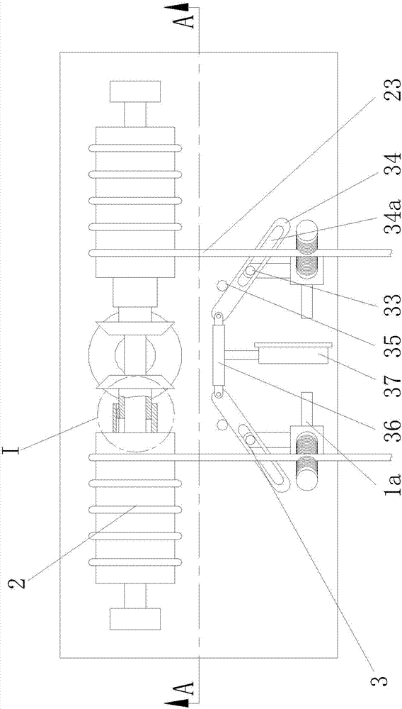
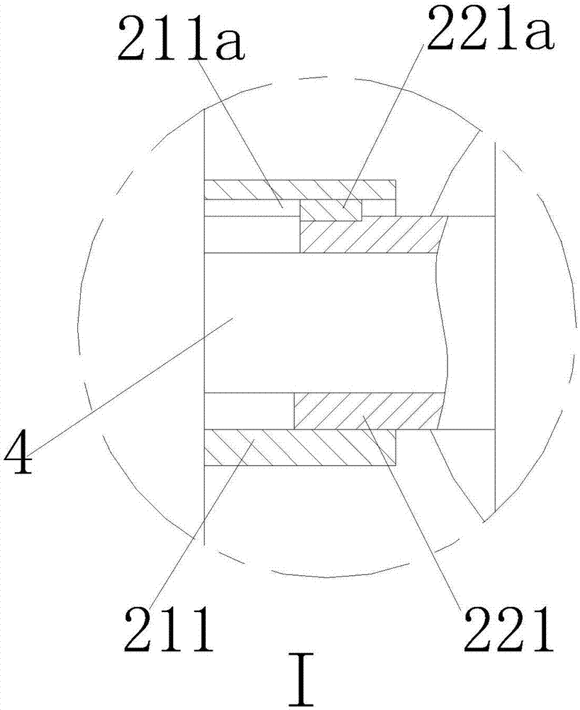
[0023] Such as Figure 1 to Figure 4 As shown, a double-drum vehicle traction system for entertainment includes a bottom plate 1 on which two wire rope winding mechanisms are arranged symmetrically. The wire rope winding mechanism includes a rear side of the bottom plate 1. The reel mechanism 2, the adjustment mechanism 3 on the front side of the bottom plate 1.
[0024] The adjustment mechanism 3 includes a movable seat 31 that is horizontally slidably installed on the bottom plate 1, a roller 32 installed on the movable seat 31 and arranged obliquely upwards away from the middle of the bottom 1, connected to the rear end of the movable seat 31 and vertically A column 33 is provided, a long plate 34 slidably fitted with the column 33 and arranged obliquely upward near the middle of the bottom plate 1, and a fixed post 35 fixed on the bottom plate 1 and abutting against the upper end of the long plate 34. The tops of the left and right long plates 34 are jointly hinged with a transition plate 36, and the transition plate 36 is connected with a hydraulic cylinder 37 that moves back and forth and is fixed on the bottom plate 1. When in use, the hydraulic cylinder 37 moves, the two long plates 34 are pushed by the transition plate 36 to rotate around the fixed column 35, and the hydraulic cylinder 37 is pushed backward, so that the long plate 34 pushes the moving seat 31 to move closer to each other, thereby realizing the reel The pitch of the wire rope 23 output in the mechanism 2 is adjusted.
[0025] The long plate 34 is provided with a bar-shaped through hole 34 a that is matched with the cylinder 33 along the length direction of the long plate 34. In use, the hydraulic cylinder 37 moves backward through the action of the bar-shaped through hole 34a, the bar-shaped through hole 34a pushes the movable seat 31 closer to each other, the hydraulic cylinder 37 moves forward, and the bar-shaped through hole 34a pushes the movable seat 31 away from each other.
[0026] The bottom plate 1 is provided with a long sliding groove 1 a that cooperates with the movable seat 31.
[0027] An annular rope groove 32 a is evenly distributed on the roller 32 along the axial direction of the roller 32. When in use, the wire rope 23 output from the reel mechanism 2 cooperates with the annular rope groove 32a to guide the wire rope 23 whose pitch is changed. At the same time, it can also be placed on the annular rope groove 32a of different heights to control the wire rope 23 Output height.
[0028] The reel mechanism 2 includes a reel 21, a small cone-shaped friction wheel 22 coaxially connected to the reel 21 and slidingly fitted with a key, a steel wire 2 wound on the reel 21, and two left and right reel mechanisms 2 The drum 21 is jointly installed with a transmission shaft 4 connected to the bottom plate 1, and the bottom of the transmission shaft 4 is provided with a large cone friction wheel 5 that cooperates with two left and right small cone friction wheels 22. The wheel 5 is connected with a motor 6, and the motor 6 is fixed with a support block 7 that is vertically slidably mounted on the bottom plate 1. The support block 7 is provided with an inclined surface 7a that is inclined to the upper right side, and the support block 7 is horizontally slidingly matched There is a trapezoidal block 8 which is connected with a hydraulic cylinder 9 fixed on the bottom plate 1. The ends of the steel ropes 23 output from the two drums 21 are located on the same horizontal plane. When in use, the motor 6 drives the large cone friction wheel 5 to rotate, and drives the two small cone friction wheels 2 to rotate, so that the two drums 21 wind up the wire rope 23. At the same time, due to the large cone friction wheel 5 and the small cone friction wheel 5 The transmission characteristics between the friction wheels 2, the two small tapered friction wheels 2 produce opposite turns to achieve the effect of towing the vehicle. The output wire rope 23 is located on the same level to facilitate the connection with the towing vehicle. The hydraulic cylinder 9 pushes After the trapezoidal block 8 moves, the supporting block 7 can be moved vertically, so that the transmission ratio between the large cone friction wheel 5 and the small cone friction wheel 22 is changed, thereby changing the winding speed of the reel 21.
[0029] A sliding sleeve 211 is fixed at one end of the reel 21 close to the motor 6, and a ring sleeve 221 that matches the sliding sleeve 211 is fixed on the small tapered friction wheel 22. The sliding sleeve 211 is provided with a sliding groove 211a, so The ring sleeve 221 is fixed with a key 221a that cooperates with the sliding groove 211a. In this way, when the transmission ratio between the large cone friction wheel 5 and the small cone friction wheel 22 is changed, the small cone friction wheels 22 on both sides will be pushed to move along the transmission shaft 4 through the sliding groove 211a and the key 221a. The cooperation of the spool 21 makes the position of the reel 21 on the transmission shaft 4 not change, and ensures the output stability of the wire rope 23.
[0030] The bottom plate 1 is provided with a vertical plate 15, the vertical plate 15 is provided with a vertical bar-shaped through hole 15a, and the left end of the support block 7 is fixed with a sliding column matching the vertical bar-shaped through hole 15a 7b. In this way, it is ensured that the supporting block 7 can slide stably on the bottom plate 1 without deflection.
[0031] The above shows and describes the basic principles, main features and advantages of the present invention. Those skilled in the industry should understand that the present invention is not limited by the above-mentioned embodiments. The above-mentioned embodiments and the specification describe only the principles of the present invention. Without departing from the spirit and scope of the present invention, the present invention will have various aspects. Various changes and improvements, these changes and improvements all fall into the claimed invention. The scope of protection claimed by the present invention is defined by the appended claims and their equivalents.

PUM

no PUM

Description & Claims & Application Information

We can also present the details of the Description, Claims and Application information to help users get a comprehensive understanding of the technical details of the patent, such as background art, summary of invention, brief description of drawings, description of embodiments, and other original content. On the other hand, users can also determine the specific scope of protection of the technology through the list of claims; as well as understand the changes in the life cycle of the technology with the presentation of the patent timeline. Login to view more.

Similar technology patents

Photoelectric sensor for position of sun

InactiveCN101650173AEffective tracking range expandedSimple structure
Owner:WUHAN UNIV OF TECH

Magnetic cooling apparatus and control method thereof

ActiveUS20130180263A1simple structure
Owner:SAMSUNG ELECTRONICS CO LTD

Dual-Drivetrain of Power-Assist Vehicle

InactiveUS20100181130A1enhance uphill momentumsimple structure
Owner:CHOU WEN CHENG

Classification and recommendation of technical efficacy words

  • Simple structure
  • easy to use

Laser assisted total joint arthroplasty

InactiveUS20090234360A1easy to use
Owner:ALEXANDER VLADIMIR

Enclosure for a portable hemodialysis system

ActiveUS20090114582A1easy to use
Owner:DEKA PROD LLP
Why Eureka
Try Eureka