Electronic load device and drive test method using same

An electronic load, driving end technology, applied in electronic circuit testing, parts of electrical measuring instruments, measuring devices, etc., can solve the problems of burning lamp beads, low test efficiency, complicated operation, etc., to improve work efficiency and accuracy, High test efficiency and accuracy, flexible operation effect

Pending Publication Date: 2018-04-06
安阳普莱电子照明有限公司
View PDF5 Cites 4 Cited by
  • Summary
  • Abstract
  • Description
  • Claims
  • Application Information

AI Technical Summary

Problems solved by technology

During the test, if the drive is not good, the lamp beads will be burned, which will not only cause safety hazards, but also waste human and financial resources.
[0003] At present, most of the electronic loads used for test drive on the market are matrix buttons, with cumbersome interfaces, cumbersome settings, and lack of protection functions, which are easy to damage
[0004] To sum up, the existing electronic load has complex structure, cumbersome operation, and single function; moreover, the test-driven method is also relatively complicated, and the test efficiency is low

Method used


Image

  • Electronic load device and drive test method using same
  • Electronic load device and drive test method using same
  • Electronic load device and drive test method using same

Examples


Embodiment Construction

[0053]The following will clearly and completely describe the technical solutions in the embodiments of the present invention with reference to the drawings in the embodiments of the present invention. Apparently, the described embodiments are only some of the embodiments of the present invention, but not all of them. Based on the embodiments of the present invention, all other embodiments obtained by persons of ordinary skill in the art without making creative efforts belong to the protection scope of the present invention.

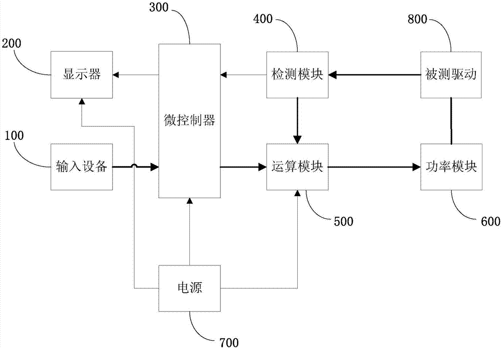
[0054] as attached figure 1 shown, with figure 1 It is a schematic structural diagram of an electronic load device according to one embodiment of the present invention, including: an input device 100, a display 200, a microcontroller 300, a detection module 400, an operation module 500, a power module 600, and a power supply 700;

[0055] The input device 100, the display 200, the detection module 400 and the operation module 500 are respectively connec...


PUM


Abstract

The invention discloses an electronic load device and a drive test method using same; the electronic load device comprises an input device, a display, a microcontroller, a detection module, an operation module, a power module, and a power supply; the input device, the display, the detection module and the operation module are respectively connected with the microcontroller; the detection module and the power module are respectively connected with the operation module; the detection module obtains the first electric signal value of a to-be-tested drive, and sends the first electric signal valueto the operation module; the operation module adjusts the first electric signal value according to the reference electric signal transmitted by the microcontroller; the detection module obtains the second electric signal value of the to-be-tested drive, and sends the second electric signal value to the microcontroller; the microcontroller sends the second electric signal value to the display fordisplaying same. The electronic load device is simple in structure, flexible in operation, can adapt to various different drive test demands, and is high in testing efficiency and accuracy.

Description

technical field [0001] The patent of the present invention relates to the technical field of driving test, in particular to an electronic load device and a method for testing driving by using the electronic load device. Background technique [0002] In the existing driving test process of, for example, LED lamps, etc., LED light source boards of various specifications often need to be welded in advance to adapt to LED lamps of different powers. During the test, if the drive is bad, the lamp beads will be burned, which will not only cause safety hazards, but also waste human and financial resources. [0003] At present, most of the electronic loads used for test driving on the market are matrix buttons, with cumbersome interfaces, cumbersome settings, and lack of protection functions, which are easy to be damaged. [0004] To sum up, the existing electronic loads have complex structures, cumbersome operations, and single functions; moreover, the test-driven method is relativ...

Claims


Application Information

Patent Timeline
IPC IPC(8): G01R1/28G01R31/28
CPCG01R1/28G01R31/282
Inventor 朱耀宗
Owner 安阳普莱电子照明有限公司
Why Eureka
Try Eureka