Bidirectional fresh air purifier

A purifier and fresh air technology, applied in ventilation system, space heating and ventilation, space heating and ventilation details, etc., can solve the problems of high electricity cost, complex structure, loud purifier operation noise, etc., and achieve extended Effect of service life, improvement of applicability, and maintenance of room temperature

Active Publication Date: 2018-04-10
KUNSHAN SILAIMU ENERGY SAVING TECH CO LTD
View PDF6 Cites 1 Cited by
  • Summary
  • Abstract
  • Description
  • Claims
  • Application Information

AI Technical Summary

Problems solved by technology

[0003] Some purifiers currently on the market have at least the following disadvantages: 1. The structure is complex, the layout is unreasonable, and it is inconvenient to use; 2. The aluminum heat exchange core is used. Condensed water is generated on the surface, which affects the working effect of the heat exchange core, and even damages the heat exchange core, shortening the service life of the two-way fresh air purifier. But this method not only increases the cost but also complicates the structure; 3. The indoor return air outlet of some purifiers is not equipped with filter elements, and the pollution particles contained in the indoor return air enter the heat exchange core, which is easy to damage the heat exchange core and shorten the The service life of the purifier; 4. The wind speed of the fan is not concentrated and uneven, which affects the effect of the purifier; 5. The pressure loss of the fan is high, and the cost of electricity is high; 6. The noise of the purifier is large
[0004] The utility model patent with the Chinese patent authorization number CN202452635U discloses a wall-mounted total heat fresh air exchanger, which can be hung on the wall and has the advantages of small size, beautiful appearance and convenient installation, but it does not solve the above-mentioned technology question

Method used


Image

  • Bidirectional fresh air purifier
  • Bidirectional fresh air purifier
  • Bidirectional fresh air purifier

Examples


Embodiment

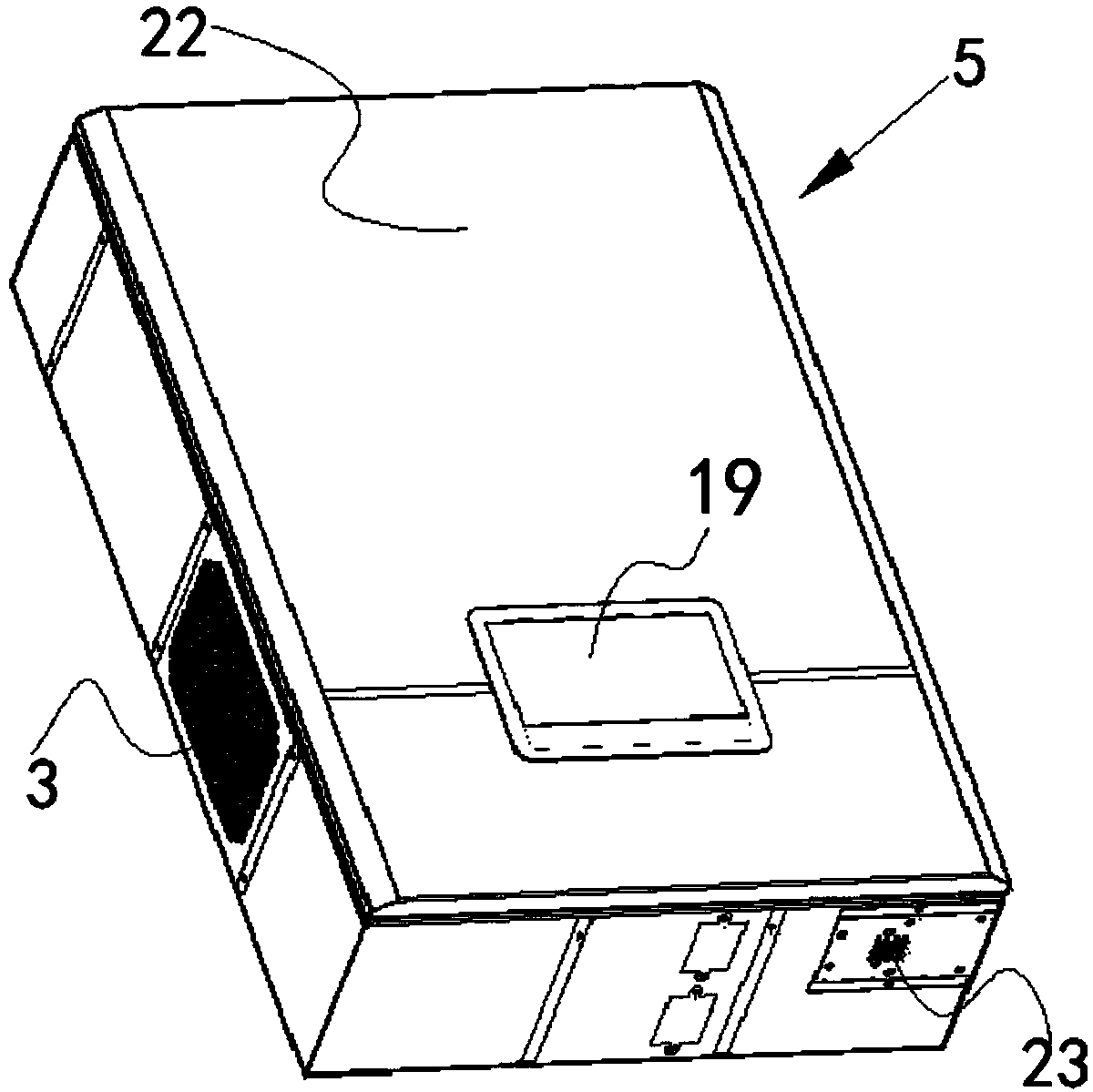
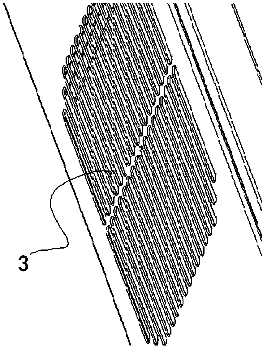
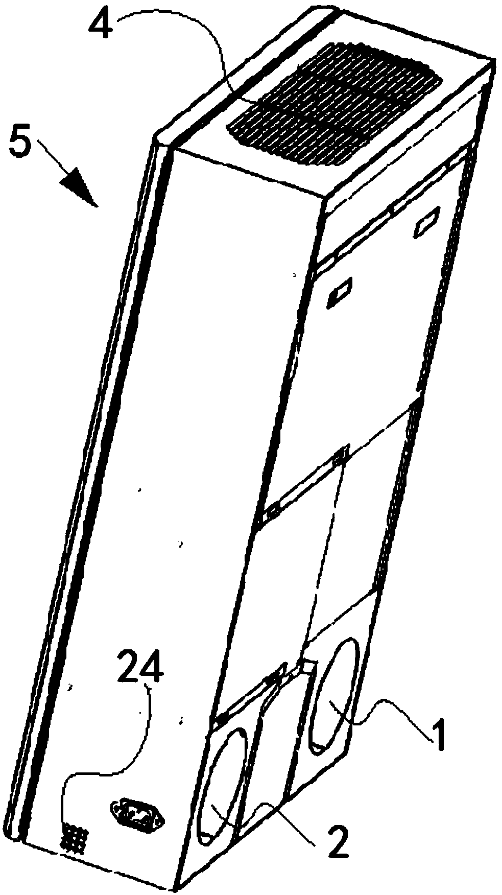
[0072] Example: A two-way fresh air purifier, such as Figure 1-12 As shown, it includes a shell 5, an outdoor air inlet 1, an outdoor air outlet 2, an indoor return air outlet 3, an indoor air supply outlet 4, a heat exchange core 9 and an electrical control box 6. The height direction of the shell is defined as the up and down direction The width direction is defined as the left and right direction and the thickness direction is defined as the front and rear direction. The outdoor air outlet and the outdoor air inlet are respectively located at the lower end and the rear end of the housing, and the indoor return air outlet is located at the rear of the housing. At the right end, the indoor air outlet is located at the upper end of the housing, the heat exchange core is located at the middle and right end of the housing, and the electrical control box is located at the lower end of the housing;

[0073] The heat exchange core is provided with fresh air ducts 91 and return air du...


PUM


Abstract

The invention discloses a bidirectional fresh air purifier. The bidirectional fresh air purifier comprises a shell, an outdoor air inlet, an outdoor air outlet, an indoor air return port, an indoor air supply port, a heat exchange core and an electric control box; the heat exchange core is provided with a fresh air hole channel and an air return hole channel; a fresh air duct is provided with theoutdoor air inlet, the fresh hole channel, an air inlet flow guide plate, an air inlet fan, a fresh air filter element and the indoor air supply port; an air return channel is provided with the indoorair return port, an air return filter element, the air return hole channel, an air return flow guide plate, an air return fan and the outdoor air outlet; the air inlet flow guide plate comprises an air inlet side flow guide inclined plate, a main air inlet guide plate and an air supply side flow guide inclined plate; the air return flow guide plate comprises an air return side flow guide inclinedplate and a main air return flow guide plate; and the electric control box comprises a control circuit board and an electrical component. The bidirectional fresh air purifier has the advantages of being relatively high in heat exchange rate and air purification rate, exquisite in structure, reasonable in arrangement, long in service life and low in cost; and air guide rings are additionally arranged, and therefore the pressure loss can be reduced, and the noise is low.

Description

Technical field [0001] The invention belongs to the technical field of air purification and ventilation, and particularly relates to a two-way fresh air purifier. Background technique [0002] The purifier injects outdoor air into the room after dust removal, temperature adjustment, and humidity adjustment, replacing the turbid indoor air, and maintaining the circulation of indoor and outdoor air, thereby improving indoor air quality and providing fresh air for human health. The fresh air sent into the room through this system will gradually replace the dirty indoor air, thereby improving the indoor air quality. [0003] Some purifiers currently on the market have at least the following shortcomings: First, the structure is complex, the layout is unreasonable, and it is not convenient to use; Second, the aluminum heat exchange core is used, and the aluminum heat exchange core works for a period of time. Condensation water is generated on the surface, which affects the working effe...

Claims


Application Information

Patent Timeline
Patent Type & Authority Applications(China)
IPC IPC(8): F24F7/08F24F3/16F24F11/84F24F12/00F24F13/08F24F110/64F24F110/70F24F140/12
CPCF24F7/08F24F12/006F24F13/08F24F8/10F24F8/158
Inventor 戴文薛健朱蓓蕾
Owner KUNSHAN SILAIMU ENERGY SAVING TECH CO LTD
Why Eureka
Try Eureka