

Novel stainless steel side wall structure and mounting method of novel stainless steel side wall
A side wall structure, stainless steel technology, applied in the direction of transportation and packaging, railway car body parts, railway car body, etc., can solve the problems that the flatness of the side wall is difficult to guarantee, affect the appearance quality of the car body, and the tooling structure is complicated, etc., to achieve improvement Assembling production efficiency, ensuring the appearance quality of the car body, and reducing the effect of the process
- Summary
- Abstract
- Description
- Claims
- Application Information
AI Technical Summary
Problems solved by technology
Method used
Image

Examples
Embodiment 1
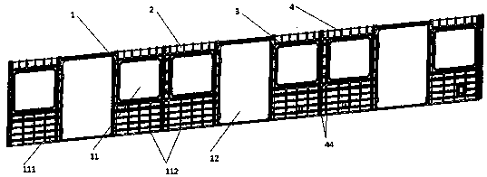
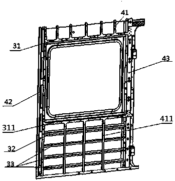
[0031] Such as figure 1 , 2 , 3 and 4 show a new type of stainless steel side wall structure, including a side wall frame 1 and a side wall panel 2. The side wall panel 2 is formed by laser blanking and then laser welding in consideration of the size of the panel, and the mechanization efficiency is high. , the shape is beautiful; the exterior of the side wall frame 1 is welded with side wall panels 2, and a plurality of window frames 11 and door frames 12 are provided in the side wall frame 1, and the side wall panels 2 are provided with window frames 11 1. The opening corresponding to the door frame 12. The side wall skeleton 1 is connected by a plurality of horizontally arranged beams 3 and a plurality of longitudinally arranged columns 4. The left and right sides of the frame 1 are respectively provided with end columns 43, the left and right sides of the door frame 12 are respectively provided with door columns 42, a window upper beam 31 is arranged above the window fram...
Embodiment 2
[0034] Such as figure 1 As shown, the side wall skeleton includes a first skeleton wall 111 with a single window frame 11 and a second skeleton wall 112 with two adjacent window frames 11, and there are two first skeleton walls 111, which are respectively installed At the left and right ends of the side wall frame 1, there are multiple second frame walls 112 installed between the two first frame walls 111, and between the first frame walls 111 and the second frame walls 112 there are A door frame 12 is provided between the plurality of second skeleton walls 112 .
[0035] Such as figure 1 and Figure 5 As shown, two window columns 44 are arranged between the two window frames 11 in the second skeleton wall 112, and the two window columns 44 pass through the window upper beam 31 and the window lower beam. 311, corresponding card slots 9 are respectively set on the connection positions between the window column 44 and the window upper beam 31 and the window lower beam 311, an...
Embodiment 3
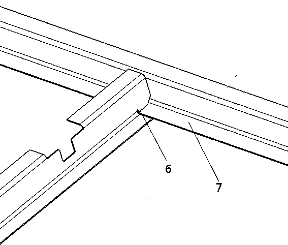
[0039] Such as Figure 6 As shown, the lower beam 311 under the window, the upper beam 31, the beam 34 between the windows, the column 44 between the windows, the column 41 on the window and the column under the window are Z-shaped steel profiles, and the waist beam 32 and the door column 42 are several Shaped steel profile, the end column 43 is a profile made of a several-shaped steel and an L-shaped steel connected to the side of the several-shaped steel, the flat plate of the L-shaped steel is flush with the protrusion of the several-shaped steel, so Described lower crossbeam 33 is by a circular arc-shaped arc plate 5, and the side portion of arc plate 5 is connected with the section material that side plate 7 is formed, and the structure of arc plate 5 of described lower crossbeam 33 in the present invention has strong compression resistance. Advantages, under the condition of satisfying the strength and rigidity of the car body, less materials are used and the weight is l...
PUM
 Abstract
Description
Claims
Application Information