Siphon floor drain

A floor drain and siphon technology, applied in the field of bathroom accessories, can solve the problems of narrow water flow channels, easy to throw away and bend the buckled bowl, and achieve the effect of improving adaptability

Pending Publication Date: 2018-04-13
开平市瑞霖淋浴科技有限公司
View PDF0 Cites 2 Cited by
  • Summary
  • Abstract
  • Description
  • Claims
  • Application Information

AI Technical Summary

Problems solved by technology

[0003] The national standard for the water seal height of the floor drain is 50mm, but the water seal height of most water-sealed floor drains on the market is only 10-20mm, and the anti-odor effect is poor; the traditional water-sealed floor drain is a bell-shaped structure, that is, a buckle bowl (bell) is used Buckle on the mouth of the downpipe to create a "U"-shaped trap to achieve the purpose of sealing, so it is called "water seal"
According to the survey, the bell-type floor drain has the disadvantages of shallow water seal and easy throwing of bowls. In the toilets of many hotels,

Method used


Image

  • Siphon floor drain
  • Siphon floor drain
  • Siphon floor drain

Examples


Embodiment 1

[0028] Embodiment 1 A kind of siphon floor drain

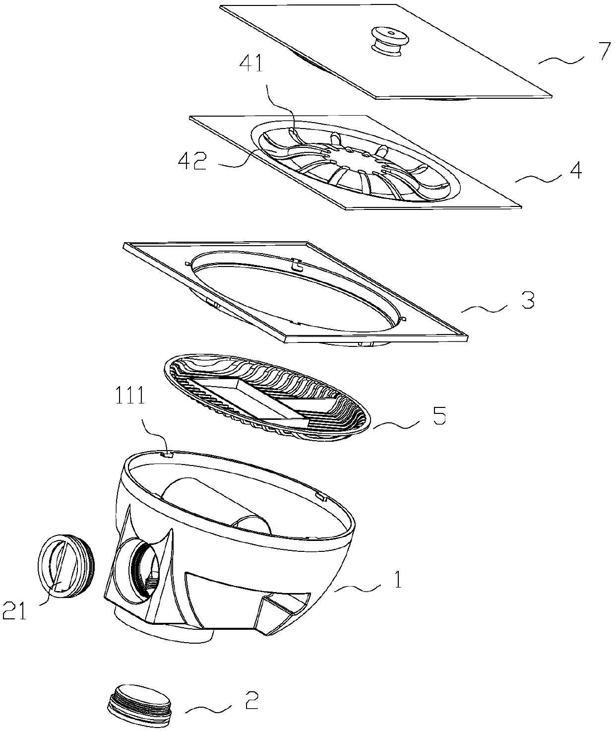
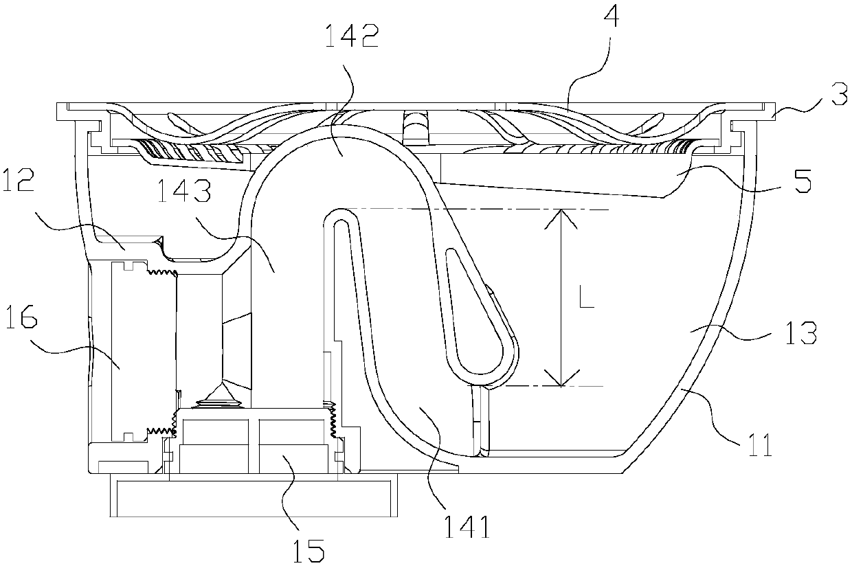
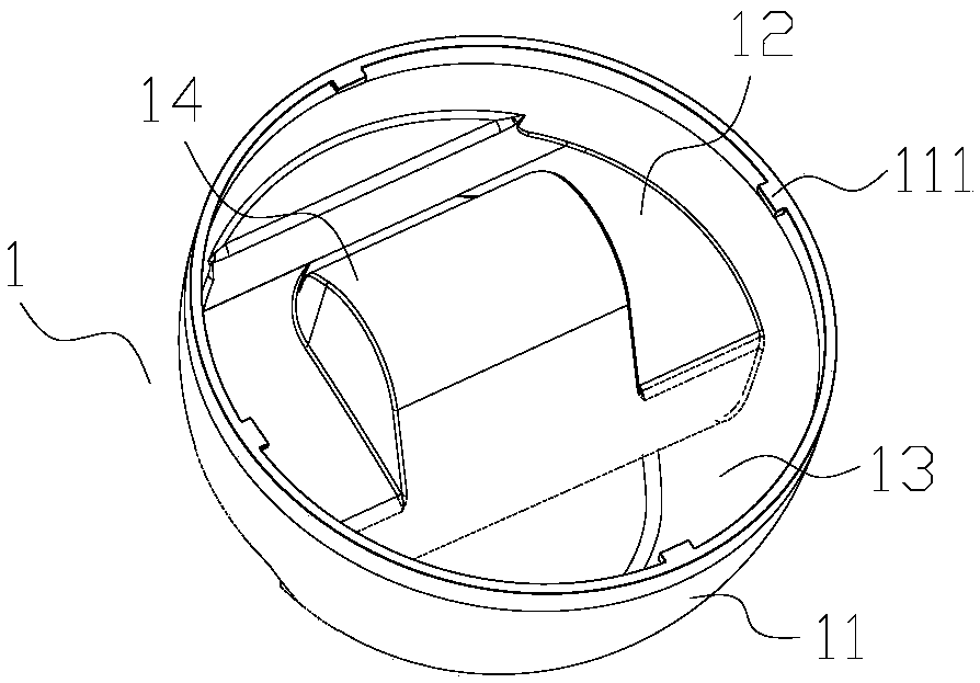
[0029] like Figure 1-6 As shown, the siphon floor drain includes a siphon body 1 and a plug 2; the siphon body is a shell 11 with an upper opening, one side of the shell cavity is provided with a drain table 12, and the other side of the shell cavity is a trap 13. An inverted U-shaped flat siphon 14 is provided on the discharge platform, and the flat siphon includes a water inlet pipe 141, an elbow 142 connected to the end of the water inlet pipe, and an outlet pipe 143 connected to the end of the elbow; The elbow is protruded on the discharge platform, the inlet pipe is connected with the outlet of the water trap, and the end of the outlet pipe is provided with a straight outlet 15 and a horizontal outlet 16; the plug is installed on the straight outlet or the horizontal outlet. on the drain.

[0030] This application adopts the principle of toilet siphon. On the one hand, an inverted U-shaped flat siphon and trap are arra...

Embodiment 2

[0040] Embodiment 2 A siphon floor drain applied to a washing machine

[0041] like Figure 6-9 As shown, the present invention also provides a siphon floor drain applied to a washing machine. Specifically, the siphon floor drain also includes a snap-in sleeve 6 arranged between the grate and the garbage filter on the basis of the embodiment; The in-type casing includes a mounting plate 61 and a pipe body 62 arranged on the mounting plate; the mounting plate is provided with radial drainage holes to facilitate drainage; the outer peripheral edge of the mounting plate is provided with a limit bump 611, The tray is provided with a guide groove 35 for installing the limit protrusion and an L-shaped limit groove 36 for limiting the movement of the limit protrusion; the guide groove is connected with the L-shaped limit groove; the guide groove is located on the hollow tray The upper surface of the upper surface of the L-shaped limit groove is located on the annular installation ri...


PUM

PropertyMeasurementUnit
Lengthaaaaaaaaaa

Abstract

The invention discloses a siphon floor drain, comprising a siphon type main body and a plug; the siphon type main body is a casing with an upper opening, one side of the inner cavity of the casing is provided with a water discharge table, and the other side of the inner cavity of the casing is a water trap; An inverted U-shaped flat siphon pipe is arranged on the water table, and the flat siphon pipe includes a water inlet pipe, a curved pipe connected to the end of the water inlet pipe, and a water outlet pipe connected to the end of the curved pipe; The water pipe is communicated with the outlet of the water trap, and the end of the water outlet pipe is provided with a straight water outlet and a horizontal water outlet; the plug is installed on the straight water outlet or the horizontal water outlet. This application adopts the principle of toilet siphon type, and sets up an inverted U-shaped flat siphon pipe and a water trap on the siphon type body, so as to perfectly realize the design of the siphon pipe in the smallest space possible, and can achieve a higher flow rate when the water volume surges. On the other hand, due to the function of the water trap, it can prevent the odor blocking the sewer from going up.

Description

technical field [0001] The invention relates to a sanitary fitting technology, in particular to a siphon floor drain. Background technique [0002] At present, the floor drain is an important interface connecting the sewer system and the indoor ground. As an important part of the residential drainage system, its performance directly affects the quality of the indoor air, and is even very important to the healthy life quality of the people in the house. [0003] The national standard for the water seal height of the floor drain is 50mm, but the water seal height of most water-sealed floor drains on the market is only 10-20mm, and the anti-odor effect is poor; the traditional water-sealed floor drain is a bell-shaped structure, that is, a buckle bowl (bell) is used Buckle on the mouth of the downpipe to create a "U"-shaped trap to achieve the purpose of sealing, so it is called "water seal". According to the investigation, the bell-type floor drain has shallow water seal and t...

Claims


Application Information

Patent Timeline
IPC IPC(8): E03F5/04E03F5/06
CPCE03F5/0407E03F5/041E03F5/06
Inventor 梁巨超
Owner 开平市瑞霖淋浴科技有限公司
Why Eureka
Try Eureka