
A method and device for adjusting the focal length of a microlens array

A micro-lens array and micro-mirror array technology, which is applied in the field of micro-optical elements, can solve the problems of complex structure of adjustable focus micro-lenses, and achieve the effects of simple structure, convenient operation and fast adjustment speed.

Inactive Publication Date: 2020-08-28
CHENGDU UNIV OF INFORMATION TECH
View PDF12 Cites 0 Cited by
  • Summary
  • Abstract
  • Description
  • Claims
  • Application Information

AI Technical Summary

Problems solved by technology

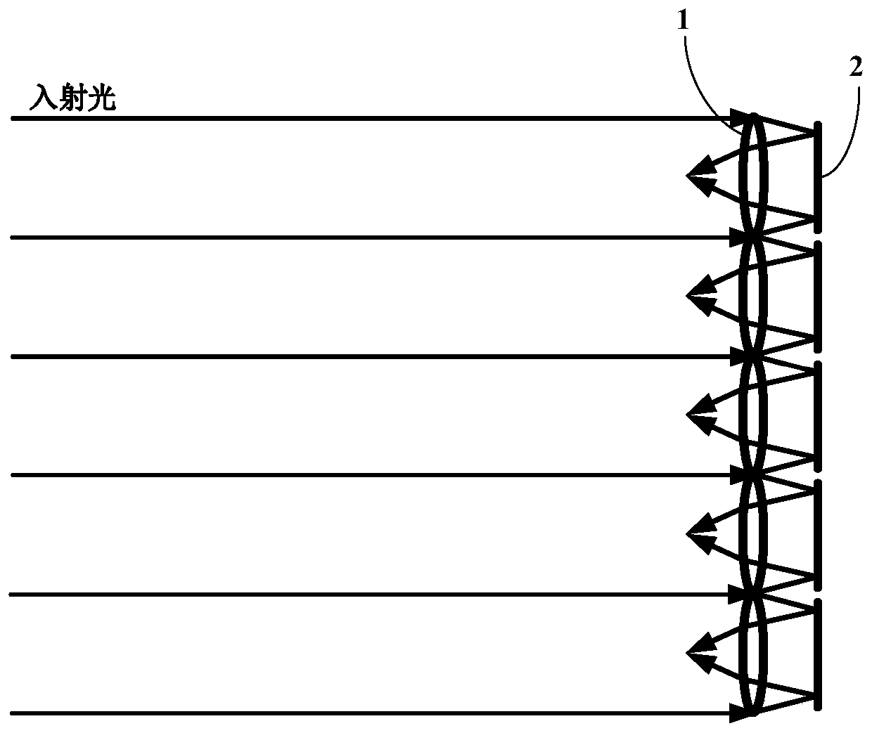
[0005] In order to solve the above technical problems, the present invention provides a method and device for adjusting the focal length of a microlens array. The focusing method is simple and convenient, and solves the current problem that the structure of the adjustable focus microlens is complex and there is no adjustable focus microlens array.

Method used


Image

  • A method and device for adjusting the focal length of a microlens array
  • A method and device for adjusting the focal length of a microlens array
  • A method and device for adjusting the focal length of a microlens array

Examples


Embodiment 1

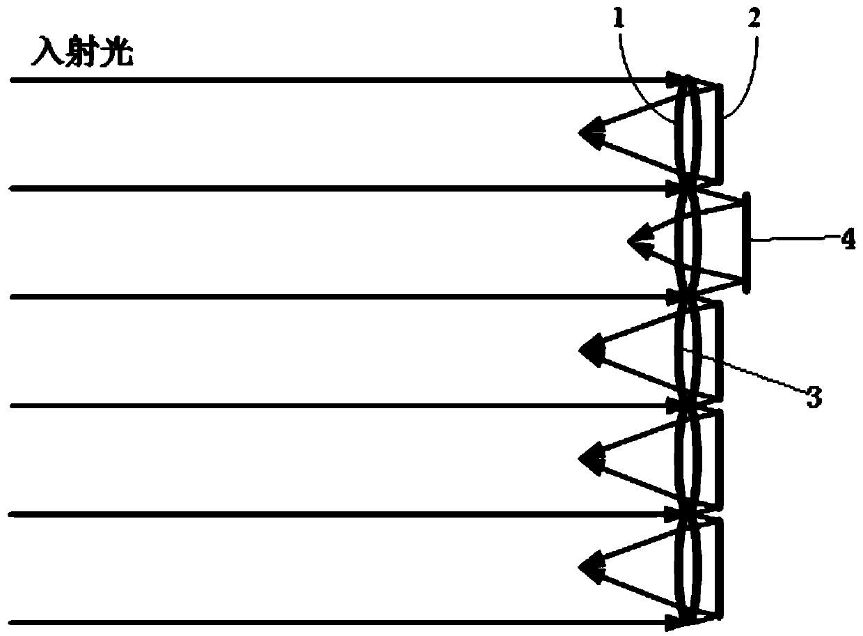
[0029] The device for adjusting the focal length of the microlens array includes a microlens array and a micromirror array. The microlens array and the micromirror array have the same unit spacing. The incident light is divided and converged after passing through the microlens array, and then enters the micromirror array. The surface is reflected, so that it passes through the microlens array again and finally converges into an array of light spots in front of the microlens array. Each micromirror of the micromirror array can move back and forth along the optical axis, thereby changing the position of the focused light spot, and realizing the adjustment and change of the focal length of the microlens array. The number of micromirrors moving back and forth is 1 or several, and the focal length of individual or several microlenses is changed; the micromirrors are transmissive.

[0030] Such as figure 1 The method for adjusting the focal length of the microlens array in the pres...

Embodiment 2

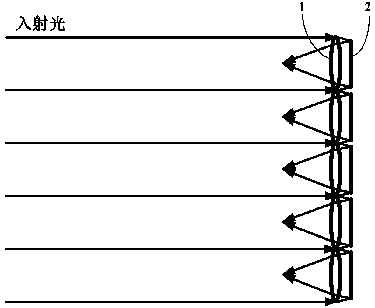
[0033] Other content is as content in embodiment 1, and the present invention also can change the focal length of all microlenses with the same size simultaneously by all micromirrors all moving the same size distance at the same time, as image 3 shown. The microlens array is a refractive microlens array.

Embodiment 3

[0035] Other content is as content in embodiment 1, and the present invention also can change the focal length of all microlenses with the same size simultaneously by all micromirrors all moving the same size distance at the same time, as image 3 shown. The microlens array can also be a diffractive microlens array to accomplish the same function, such as Figure 6 shown. Refractive microlenses and diffractive microlenses have their own advantages and disadvantages, and can be selected according to different situations and application fields.


PUM


Abstract

The present invention relates to the technical field of micro-optical elements, in particular to a method and device for adjusting the focal length of a micro-lens array, which includes a micro-lens array, the micro-lens array is provided with micro-lenses, and is characterized in that: a micro-mirror array is also provided, and a micro-lens array is provided. The mirror array is provided with micromirrors, and each micromirror of the micromirror array moves back and forth along the optical axis, so as to change the position of the focused light spot and realize the adjustment and change of the focal length of the corresponding microlens. The device for applying the method includes a microlens array and a micromirror array, both of which have the same cell pitch. The incident parallel light will first pass through the microlens array, then be reflected by the microlens array, pass through the microlens array in the opposite direction, and finally converge into a spot array, and its cell pitch is also equal to the cell pitch of the microlens array. The invention solves the problem that the microlens array cannot be adjusted, and has simple method and convenient operation.

Description

technical field [0001] The invention relates to the technical field of micro-optical elements, in particular to a method and a device for adjusting the focal length of a micro-lens array. Background technique [0002] The microlens array used to divide and focus the light beam is one of the important devices in the field of micro optics. Widely used in many fields. [0003] The microlens array is an array composed of lenses with a clear aperture and a relief depth of micron, that is, the same lenses are arranged on a plane at a certain period to form a lens array. It not only has the focusing, imaging, etc. It has basic functions, and has the characteristics of small unit size and high integration, so that it can complete the functions that traditional optical components cannot complete, and can form many new optical systems. [0004] At present, the focal length of most microlens arrays is fixed after the processing is completed, so the optical properties and functions ar...

Claims


Application Information

Patent Timeline
Patent Type & Authority Patents(China)
IPC IPC(8): G02B7/10
CPCG02B7/10
Inventor 马文英汪为民
Owner CHENGDU UNIV OF INFORMATION TECH
Learn More