Control method and system of single photon detector death time

A single-photon detector and time-of-death technology, applied in transmission systems, digital transmission systems, and key distribution, can solve the problems of easy sliding of potentiometer knobs, heavy workload, increased labor workload, etc., to achieve convenient adjustment and stability good sex effect

Inactive Publication Date: 2018-04-13
浙江科易理想量子信息技术有限公司
View PDF0 Cites 2 Cited by
  • Summary
  • Abstract
  • Description
  • Claims
  • Application Information

AI Technical Summary

Problems solved by technology

But there will be a problem in the dead time control circuit. When the efficiency value and dark count value of the single photon detector need to be adjusted, it is often necessary to adjust the value of R in the RC circuit (keep the capacitance of the capacitor unchanged). When adjusting a suitable When the value of the dead time is large, the resistance needs to be replaced continuously
The most difficult problem is: when the entire quantum key distribution device has been assembled, it is necessary to open the device when adjusting the resistance of the dead time circuit RC, which increases the workload
However, there are also disadvantages in the use of potentiometers: first, the potentiometer will deviate from the original set value under the condition of handling and vibration (the main reason is that the knob of the potentiometer is easy to slide), causing the dead time to deviate from the set value, Thus affecting the performance of single photon detectors
At the same time, the system must also open the device when adjusting the value of the dead time, which is very troublesome and requires a large workload

Method used


Image

  • Control method and system of single photon detector death time
  • Control method and system of single photon detector death time

Examples


Embodiment Construction

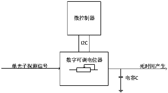
[0020] Such as figure 1 and figure 2 As shown, in this embodiment, the control system of the death time of the single photon detector includes: a microcontroller, which is used to adjust and control the system; a digital adjustable potentiometer, connected to the microcontroller; a capacitor, connected to the microcontroller The digital adjustable potentiometer is connected; wherein, the digital adjustable potentiometer is also provided with rewritable registers.

[0021] Specifically, in the control system of the death time of the single photon detector, the microcontroller is connected to the digital adjustable potentiometer through a serial communication interface, and the digital adjustable potentiometer is connected to one of the capacitors The polar plate is connected, and the other polar plate of the capacitor is grounded.

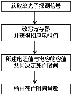
[0022] When working, the digital adjustable potentiometer receives a single photon detection signal, adjusts the microcontroller, and the microc...


PUM


Abstract

The invention discloses a method for controlling the death time of a single-photon detector, which is characterized in that it comprises the following steps: obtaining a single-photon detection signal; rewriting a register and obtaining a corresponding resistance value; the resistance value and the capacitance jointly determine the death time According to the invention, the value of the dead time of the single photon detector in the quantum key distribution system can be adjusted conveniently, and the stability is better.

Description

【Technical field】 [0001] The invention relates to the field of communication, in particular to quantum communication. 【Background technique】 [0002] In recent years, due to the frequent occurrence of information leakage, eavesdropping and other incidents, information security has received widespread attention. More and more enterprises and institutions have strengthened security protection in information transmission and communication, and many information encryption and secure communication methods , Quantum encryption communication is regarded as one of the safest encrypted communication methods at present. [0003] In quantum communication technology, single photon detector is the key device in the whole quantum key communication equipment. The performance of the single photon detector directly determines the security and key generation rate of the quantum key distribution system. The quantum key distribution system mainly realizes the safe generation of keys through q...

Claims


Application Information

Patent Timeline
Patent Type & Authority Applications(China)
IPC IPC(8): H04L9/08
CPCH04L9/0852H04L9/0855
Inventor 徐生福
Owner 浙江科易理想量子信息技术有限公司
Why Eureka
Try Eureka