Welding gun deviation three-dimensional extraction method for sheet welding based on passive vision sensing
A visual sensing and thin plate welding technology, which is applied in welding equipment, arc welding equipment, manufacturing tools, etc., can solve the problems of unrealized three-dimensional deviation, low welding efficiency, and low welding quality, so as to improve welding quality, accuracy, high precision effect
- Summary
- Abstract
- Description
- Claims
- Application Information
AI Technical Summary
Problems solved by technology
Method used
Image
Examples
Embodiment 1
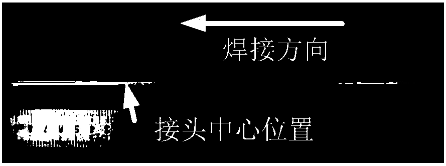
[0021] 1. Select a thin plate with a thickness of about 4mm, and select its welding area, such as image 3 As shown, automatic welding of thin plate and thin plate robot arc welding is adopted;
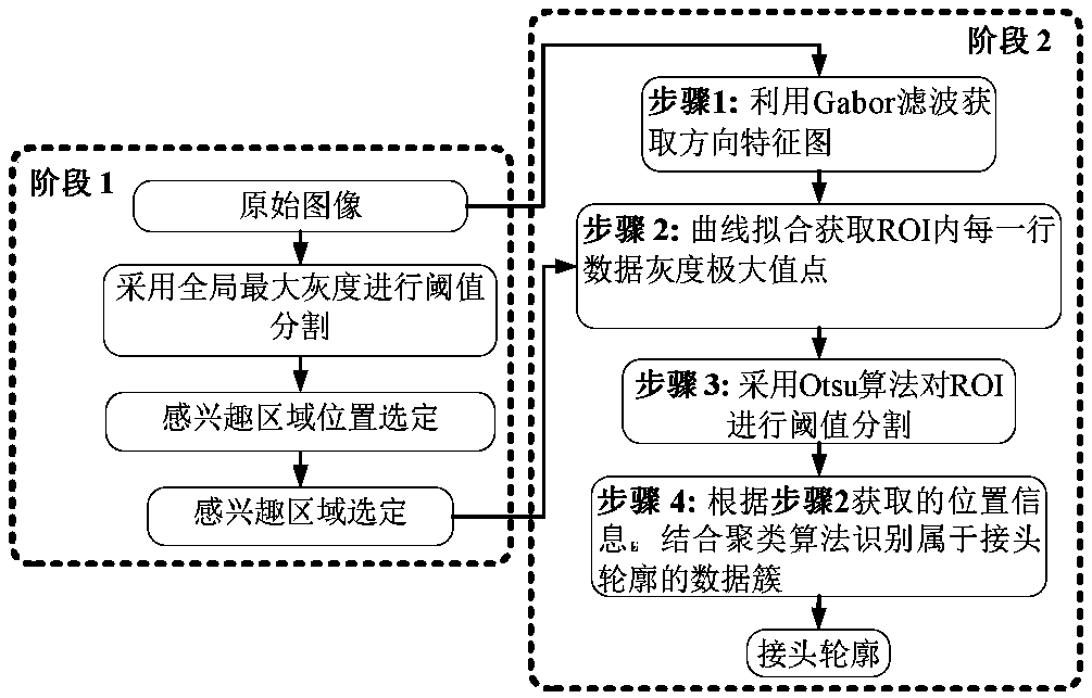
[0022] 2. Using a visual sensing device that includes a combination of a filter (the center wavelength is 660nm, and a half width is 20nm) and a light-reducing film (the transmittance is 0.040%), the image of the weld seam is collected, and the image includes the arc area, Weld edge, joint contour line, and use Gabor filter to obtain the direction feature map of the complete weld image, retain the direction feature map of ROI, and the gray value of other areas is processed as 0, such as Figure 4 shown;
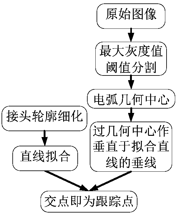
[0023] 3. Perform the following operations on the weld image collected in 2: perform polynomial fitting on the row data of the ROI multiple times and obtain the position of the maximum gray value point of each time, and perform Otsu threshold segmentation on the direction feature ma...
Embodiment 2
[0026] 1. Select a thin plate with a thickness of about 4mm, and select its welding area, such as image 3 As shown, automatic welding of thin plate and thin plate robot arc welding is adopted;
[0027] 2. Adopt a visual sensing device including a combination of a filter (the central wavelength is 660nm, and a half width is 20nm) and a light-reducing film (the transmittance is 0.014%) to collect an image of the weld seam, and the image includes the arc area, Weld edge, joint contour line, and use Gabor filter to obtain the direction feature map of the complete weld image, retain the direction feature map of ROI, and the gray value of other areas is processed as 0, such as Figure 7 as shown in (a);
Embodiment 3
[0029] 1. Select a thin plate with a thickness of about 4mm, and select its welding area, such as image 3 As shown, automatic welding of thin plate and thin plate robot arc welding is adopted;
[0030] 2. Using a visual sensing device that includes a combination of a filter (the center wavelength is 660nm, and a half width is 20nm) and a light-reducing film (the transmittance is 0.040%), the image of the weld seam is collected, and the image includes the arc area, Weld edge, joint contour line, and use Gabor filter to obtain the direction feature map of the complete weld image, retain the direction feature map of ROI, and the gray value of other areas is processed as 0, such as Figure 7 as shown in (b);
PUM
| Property | Measurement | Unit |
|---|---|---|
| wavelength | aaaaa | aaaaa |
| thickness | aaaaa | aaaaa |
Abstract
Description
Claims
Application Information
 - R&D
- Intellectual Property
- Life Sciences
- Materials
- Tech Scout
- Unparalleled Data Quality
- Higher Quality Content
- 60% Fewer Hallucinations
Browse by: Latest US Patents, China's latest patents, Technical Efficacy Thesaurus, Application Domain, Technology Topic, Popular Technical Reports.
© 2025 PatSnap. All rights reserved.Legal|Privacy policy|Modern Slavery Act Transparency Statement|Sitemap|About US| Contact US: help@patsnap.com


