
High-efficiency permanent magnetic motor

A permanent magnet motor, high-efficiency technology, applied in electrical components, electromechanical devices, electric components, etc., can solve the problems of inconvenient maintenance, reduced work efficiency, and inability to meet the disassembly and assembly of permanent magnet motors, to avoid inconvenient disassembly, The effect of reducing work efficiency

Active Publication Date: 2018-04-17
宁波江宇电器有限公司
View PDF17 Cites 6 Cited by
  • Summary
  • Abstract
  • Description
  • Claims
  • Application Information

AI Technical Summary

Problems solved by technology

[0002] The permanent magnet motor is a rectangular pulse wave, current sine wave current, hybrid permanent magnet motor form, the form of the permanent magnet motor is: 1 rectangular pulse wave current, permanent magnet brushless DC motor PMBDC has a rectangular pulse wave current, 2 Sine wave current, permanent magnet reluctance synchronous motor PSM has sine wave current, 3 hybrid permanent magnet motors, such as the patent application number 201320727448.4, this patent cannot effectively waterproof the permanent magnet motor, and it is easy to cause damage to the permanent magnet motor , unable to meet the protection of the permanent magnet motor, resulting in damage to the motor under the action of external force, affecting the use efficiency of the permanent magnet motor, unable to meet the disassembly and assembly of the permanent magnet motor at any time, inconvenient maintenance, resulting in wasting most of the time for maintenance ,decrease productivity

Method used


Image

  • High-efficiency permanent magnetic motor
  • High-efficiency permanent magnetic motor
  • High-efficiency permanent magnetic motor

Examples


Embodiment Construction

[0021] The following will clearly and completely describe the technical solutions in the embodiments of the present invention with reference to the accompanying drawings in the embodiments of the present invention. Obviously, the described embodiments are only some, not all, embodiments of the present invention. Based on the embodiments of the present invention, all other embodiments obtained by persons of ordinary skill in the art without making creative efforts belong to the protection scope of the present invention.

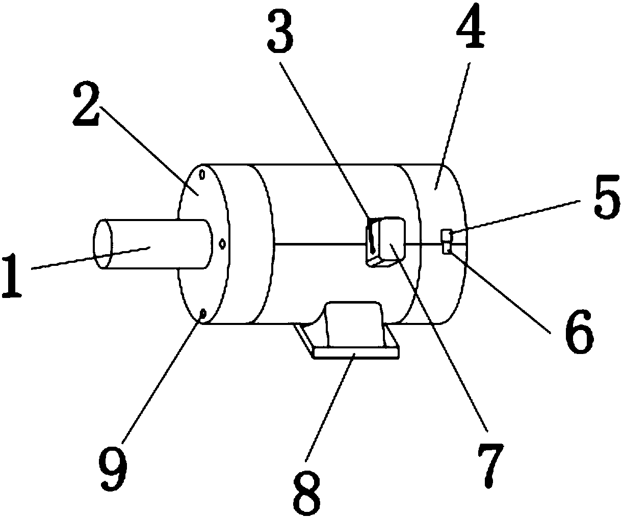
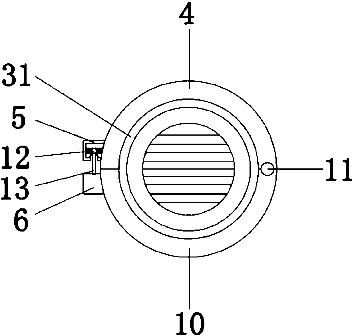
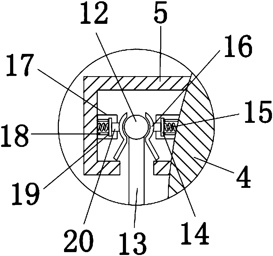
[0022] see Figure 1-5 , the present invention provides a technical solution: a high-efficiency permanent magnet motor, including a permanent magnet motor 1, the permanent magnet motor 1 is connected to an external power supply and starts to work, and the left side of the outer wall of the permanent magnet motor 1 is sleeved with a front side plate 2, The front side plate 2 is used to fix the permanent magnet motor 1 through the rivet 9, and is used to fix the...


PUM


Abstract

The invention discloses a high-efficiency permanent magnetic motor. The permanent magnetic motor is included, the left side of the outer wall of the permanent magnetic motor is sleeved by a front sideplate, the front side plate is connected with the permanent magnetic motor via rivets, the upper and lower ends of the right side of the front side plate are provided with first and second clamping casings respectively, the first clamping casing is connected to the second clamping casing via a hinge, the left side of the second clamping casing is provided with a first connecting block, the top end of the first connecting block is provided with a vertical rod, and the top end of the vertical rod is provided with a clamping ball. According to the high-efficiency permanent magnetic motor, spongeis fixed to the inner wall of the first and second clamping casings, the permanent magnetic motor is waterproof, water is absorbed in the sponge, the permanent magnetic motor rotates and generates heat to dry the sponge, use of the permanent magnetic motor is not influenced, damage on the permanent magnetic motor caused by water falling on the motor during working is avoided, and the permanent magnetic motor is prevented from influence of shaking on normal work.

Description

technical field [0001] The invention relates to the technical field of high-efficiency permanent magnet motors, in particular to a high-efficiency permanent magnet motor. Background technique [0002] The permanent magnet motor is a rectangular pulse wave, current sine wave current, hybrid permanent magnet motor form, the form of the permanent magnet motor is: 1 rectangular pulse wave current, permanent magnet brushless DC motor PMBDC has a rectangular pulse wave current, 2 Sine wave current, permanent magnet reluctance synchronous motor PSM has sine wave current, 3 hybrid permanent magnet motors, such as the patent application number 201320727448.4, this patent cannot effectively waterproof the permanent magnet motor, and it is easy to cause damage to the permanent magnet motor , unable to meet the protection of the permanent magnet motor, resulting in damage to the motor under the action of external force, affecting the use efficiency of the permanent magnet motor, unable ...

Claims


Application Information

Patent Timeline
Patent Type & Authority Applications(China)
IPC IPC(8): H02K5/10H02K5/20
CPCH02K5/04H02K5/10H02K5/20H02K5/24H02K9/06Y02T10/64
Inventor 李明
Owner 宁波江宇电器有限公司
Learn More