
Energy storage molecular material, crystal dielectric layer and capacitor

A technology of molecular materials and molecular structures, applied in fixed capacitor electrodes, fixed capacitor dielectrics, fixed capacitor parts, etc., can solve problems such as unsuitable capacitors

Active Publication Date: 2018-04-17
CAPACITOR SCI
View PDF4 Cites 3 Cited by
  • Summary
  • Abstract
  • Description
  • Claims
  • Application Information

AI Technical Summary

Problems solved by technology

[0012] However, capacitors often do not store energy in the same small size or weight as batteries, or at low energy storage costs, making capacitors unsuitable for some applications, such as electric vehicles

Method used


Image

  • Energy storage molecular material, crystal dielectric layer and capacitor
  • Energy storage molecular material, crystal dielectric layer and capacitor
  • Energy storage molecular material, crystal dielectric layer and capacitor

Examples


Embodiment 1

[0110] This example describes porphyrin-(phenyl-perylenediimides) represented by general structure I comprising fragments represented by structures 6 and 35 (Tables 1 and 5) 4 - compound (TPP-PD I 4 ) synthesis method,

[0111]

[0112] The method includes several steps.

[0113] In the first step, the synthesis of 1,7-dibromobi-3,4:9,10-tetracarboxylic dianhydride represented by the general structure 81 is carried out:

[0114]

[0115]

[0116] To this end, 3,4:9,10-perylenetetracarboxylic dianhydride (28.52 g, 72.7 mmol) was added to 420 ml of concentrated sulfuric acid and stirred at 55° C. for 24 hours. Iodine (0.685 g, 2.70 mmol) was added to the reaction mixture and stirred at 55°C for an additional 5 hours. Bromine (8.3ml, 162mmol) was added dropwise to the reaction flask over 1 hour and stirred at 85°C for 24 hours. Then with nitrogen N 2 Replace excess bromine. Water (66ml) was added dropwise to the cooled mixture and the precipitate was filtered off. ...


PUM


Abstract

The present disclosure provides an energy storage molecular material, crystal dielectric layer and capacitor which may solve a problem of the further increase of volumetric and mass density of reserved energy associated with some energy storage devices, and at the same time reduce cost of materials.

Description

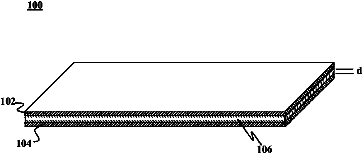
Background technique [0001] A capacitor is a passive electronic component used to store energy in the form of an electrostatic field and includes a pair of electrodes separated by a dielectric layer. When there is a potential difference between the two electrodes, an electric field exists in the dielectric layer. An ideal capacitor is characterized by a single constant value of its capacitance. It is the ratio of the charge on each electrode to the potential difference between them. In fact, the dielectric layer between the electrodes is capable of passing a small amount of leakage current. The electrodes and leads introduce an equivalent series resistance, and the dielectric layer places a limit on the electric field strength that leads to the breakdown voltage. The simplest energy storage device consists of two parallel electrodes separated by a dielectric layer with a dielectric constant ε, each electrode having an area S and arranged at a distance d from each other. Th...

Claims


Application Information

Patent Timeline
IPC IPC(8): H01G4/14H01G4/06C07D471/02C07D487/22
CPCC07D519/00H01G4/14H01G4/012
Inventor P·I·拉扎列夫
Owner CAPACITOR SCI
Learn More