Automatic cleaning device for piston rod of shock absorber

An automatic cleaning and piston rod technology, applied in the directions of dry gas arrangement, chemical instruments and methods, cleaning methods and utensils, etc., can solve the complex internal structure of the shock absorber core, affect the cleanliness of the shock absorber package, and affect the product. Quality accident rate and other issues, to achieve the effect of saving manpower, occupying less space, and preventing water pump failure

Pending Publication Date: 2018-04-20
NANYANG XIJIAN AUTOMOBILE SHOCK ABSORBER
View PDF8 Cites 1 Cited by
  • Summary
  • Abstract
  • Description
  • Claims
  • Application Information

AI Technical Summary

Problems solved by technology

[0002] The piston rod of the shock absorber is composed of a shock absorber core and external connections, among which the shock absorber core is composed of an internal restoration guide assembly and an external oil cylinder. The internal structure of the shock absorber core is relatively complicated, and the composition There are many parts, and the cleanliness of each component directly affects the product quality accident rate. The piston rod used in this shock absorber structure is machined from medium carbon steel. The machining process requires turning, Surface coating (electroplating), polishing, and a series of processes in piston rod processing will cause dirt on the surface of the piston rod to directly affect the cleanliness of the shock absorber assembly in the later stage. The traditional shock absorber piston rod is manually cleaned. This method is not only time-consuming and labor-intensive, but also easy to cause damage to cleaning personnel
[0003] The patent with the notification number CN 206083275 U discloses a piston rod automatic cleaning device, which includes a tank body and a conveyor chain. The tank body is divided into four tank bodies, and the conveyor chain passes through the four tank bodies in turn. A rod mounting seat is provided; a first heater and an ultrasonic cleaning machine are provided in the first tank; a second pump body is provided on the second tank body, and a first nozzle is provided at the outlet end of the second pump body; the third tank body There is a third pump body on top, the outlet end of the third pump body is provided with a second nozzle, the water inlet of the third tank body is connected to a distillation machine; the air nozzle is provided directly above the fourth tank body, and the air nozzle faces the conveying chain; the outlet end of the fourth tank is provided with a sensor, and the end of the conveying chain is provided with a discharge manipulator. This utility model can improve cleaning efficiency, but it uses a transmission device, which consumes more energy and wastes water.

Method used


Image

  • Automatic cleaning device for piston rod of shock absorber
  • Automatic cleaning device for piston rod of shock absorber
  • Automatic cleaning device for piston rod of shock absorber

Examples


Embodiment 1

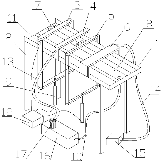
[0022] Such as figure 1 As shown, a shock absorber piston rod automatic cleaning device, the tank body 1 is arranged obliquely on a plurality of support columns 2, the first buffer frame 3, the spray device 4, the second Buffer block frame 5 and blowing device 6, on described first buffer block frame 3 and described second buffer block frame 5 all be provided with stopper 7, in described groove body 1, two horizontal bars 8 are suspended in the air, and described groove An electric push rod 9 supporting the buffer frame is arranged under the body 1, a drain hole is arranged on the bottom surface of the tank body 1, and a drain pipe 10 is connected to the drain hole, and a moving sensor 11 is arranged on the first buffer frame 3 , the motion sensor 11 and the electric push rod 9 are both electrically connected to the controller 12 .

[0023] Specifically, the spraying device 4 is a cuboid pipe arranged on the tank body, a plurality of holes are arranged on the bottom surface o...

Embodiment 2

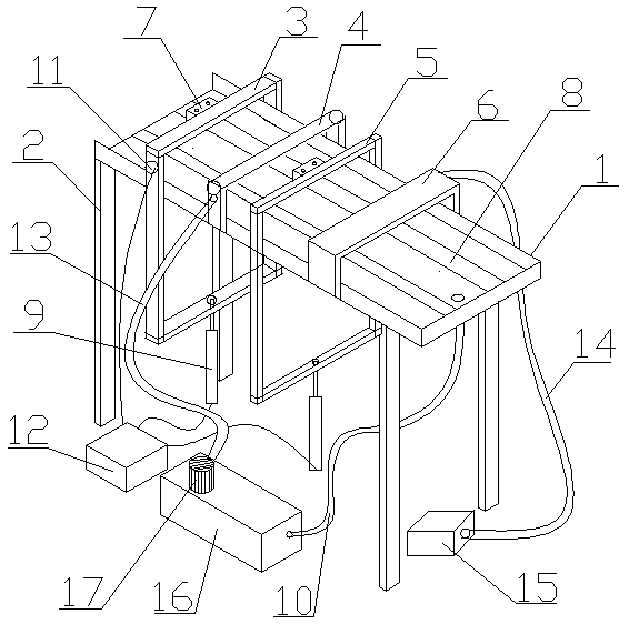
[0026] Such as figure 2 As shown, a shock absorber piston rod automatic cleaning device, the tank body 1 is arranged obliquely on a plurality of support columns 2, the first buffer frame 3, the spray device 4, the second Buffer block frame 5 and blowing device 6, on described first buffer block frame 3 and described second buffer block frame 5 all be provided with stopper 7, in described groove body 1, two horizontal bars 8 are suspended in the air, and described groove An electric push rod 9 supporting the buffer frame is arranged under the body 1, a drain hole is arranged on the bottom surface of the tank body 1, and a drain pipe 10 is connected to the drain hole, and a moving sensor 11 is arranged on the first buffer frame 3 , the motion sensor 11 and the electric push rod 9 are both electrically connected to the controller 12 .

[0027] Specifically, the spraying device 4 is a cuboid pipe arranged on the tank body, a plurality of holes are arranged on the bottom surface ...

Embodiment 3

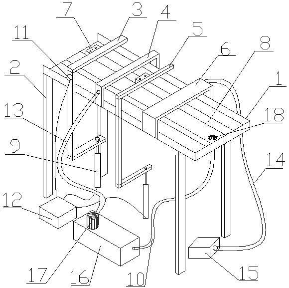
[0030] Such as image 3 As shown, a shock absorber piston rod automatic cleaning device, the tank body 1 is arranged obliquely on a plurality of support columns 2, the first buffer frame 3, the spray device 4, the second Buffer block frame 5 and blowing device 6, on described first buffer block frame 3 and described second buffer block frame 5 all be provided with stopper 7, in described groove body 1, two horizontal bars 8 are suspended in the air, and described groove An electric push rod 9 supporting the buffer frame is arranged under the body 1, a drain hole is arranged on the bottom surface of the tank body 1, and a drain pipe 10 is connected to the drain hole, and a moving sensor 11 is arranged on the first buffer frame 3 , the motion sensor 11 and the electric push rod 9 are both electrically connected to the controller 12 .

[0031]Specifically, the spraying device 4 is a cuboid pipe arranged on the tank body, a plurality of holes are arranged on the bottom surface of...


PUM


Abstract

The invention discloses an automatic cleaning device for a piston rod of a shock absorber, and belongs to the technical field of cleaning for machining. The automatic cleaning device for the piston rod of the shock absorber comprises a tank body, buffering stopper frames and a controller. A plurality of supporting columns are obliquely arranged on the tank body. The first buffering stopper frame,a spraying device, the second buffering stopper frame and an air blowing device are arranged on the tank body. Stopper blocks are arranged on the first buffering stopper frame and the second bufferingstopper frame correspondingly. Two transverse rods are arranged in the tank body in a suspended mode. Electric push rods used for supporting the buffering stopper frames are arranged below the tank body. A drain hole is formed in the bottom surface of the tank body and connected with a drain pipe. A movable inductor is arranged on the first buffering stopper frame. Both the movable inductor and the electric push rods are electrically connected with the controller. By adoption of the automatic cleaning device, the piston rod of the shock absorber can be cleaned automatically, labor is saved, the cleaning efficiency is high, and energy and water are saved.

Description

technical field [0001] The invention belongs to the technical field of mechanical processing and cleaning, and in particular relates to an automatic cleaning device for a shock absorber piston rod. Background technique [0002] The piston rod of the shock absorber is composed of a shock absorber core and external connections, among which the shock absorber core is composed of an internal restoration guide assembly and an external oil cylinder. The internal structure of the shock absorber core is relatively complicated, and the composition There are many parts, and the cleanliness of each component directly affects the product quality accident rate. The piston rod used in this shock absorber structure is machined from medium carbon steel. The machining process requires turning, Surface coating (electroplating), polishing, and a series of processes in piston rod processing will cause dirt on the surface of the piston rod to directly affect the cleanliness of the shock absorber...

Claims


Application Information

Patent Timeline
Patent Type & Authority Applications(China)
IPC IPC(8): B08B3/02B08B3/14B08B13/00F26B21/00
CPCF26B21/00B08B3/02B08B3/14B08B13/00
Inventor 肖可赵国超
Owner NANYANG XIJIAN AUTOMOBILE SHOCK ABSORBER
Why Eureka
Try Eureka