Crosshead alloy layer pouring clamp

A technology of cross head and alloy layer, applied in the direction of manufacturing tools, metal processing equipment, casting equipment, etc., can solve the problems of alloy waste, scrapping, destroying processing benchmarks, etc., to reduce the amount of alloy, ensure accuracy, and promote fluidity. Effect

Inactive Publication Date: 2018-04-20
重庆檀科科技有限公司
View PDF0 Cites 3 Cited by
  • Summary
  • Abstract
  • Description
  • Claims
  • Application Information

AI Technical Summary

Problems solved by technology

[0004] In view of this, the present invention provides a cross-head alloy layer pouring fixture to solve the problems in the prior art that there is a lot of alloy waste and damage to the processing standard, resulting in scrapping

Method used


Image

  • Crosshead alloy layer pouring clamp
  • Crosshead alloy layer pouring clamp
  • Crosshead alloy layer pouring clamp

Examples


Embodiment Construction

[0023] Hereinafter, preferred embodiments of the present invention will be described in detail with reference to the accompanying drawings. It should be understood that the preferred embodiments are only for illustrating the present invention, but not for limiting the protection scope of the present invention.

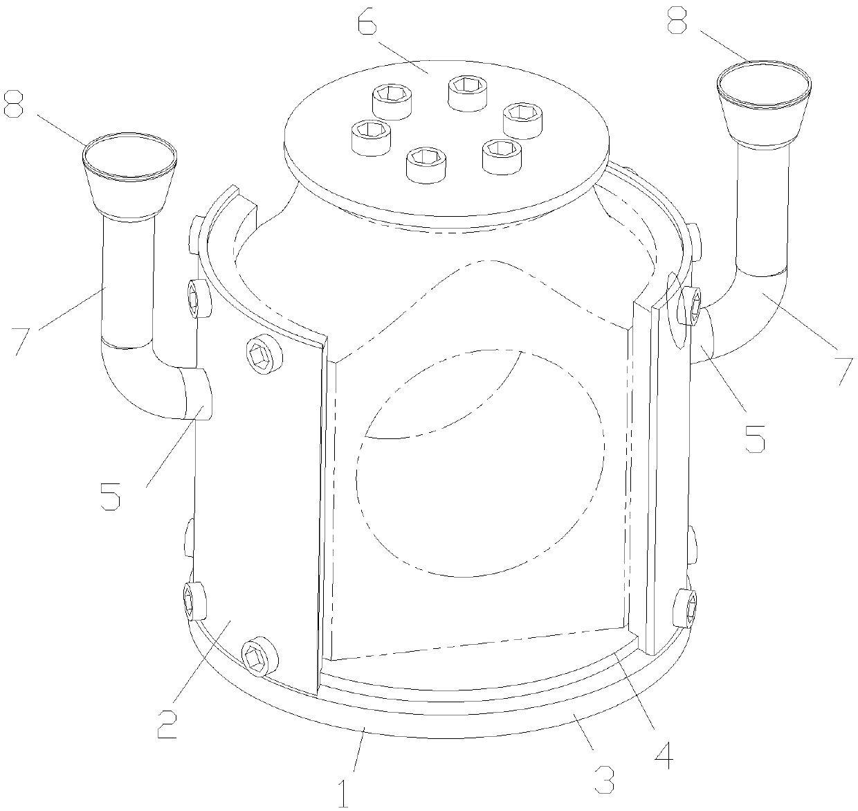
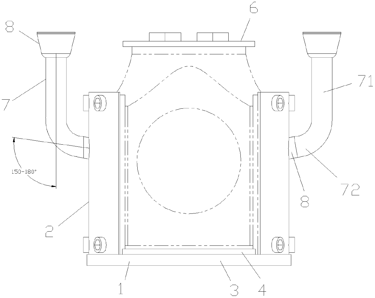
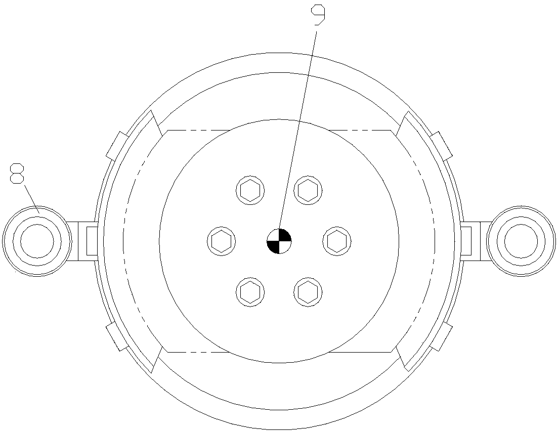
[0024] Such as Figure 1 to Figure 7 As shown, a crosshead alloy layer casting jig provided by the present invention is used for alloy casting of a crosshead, which includes a base 1 and a baffle 2, and the base includes a bottom disc 3 and is arranged on a thickness side of the bottom disc facing upward Outwardly extending spigot plug 4, the spigot plug is a cylindrical protrusion arranged coaxially with the bottom disc, the outer surface of the cylindrical protrusion can slide with the inner hole surface of the crosshead 10 large end spigot 11 Cooperate so that the large end surface of the crosshead is supported on the outer surface of the cylindrical protrusion. Op...


PUM


Abstract

The invention discloses a crosshead alloy layer pouring fixture, which belongs to the technical field of alloy processing, and comprises a base and a stopper, and the base includes a bottom disc and an outwardly extending notch arranged on a thickness side of the bottom disc. Plug, the plug plug is a cylindrical protrusion coaxial with the bottom disc, the outer surface of the cylindrical protrusion is slidably fitted with the surface of the inner hole of the big end of the crosshead, and the stopper It is tightly sealed with the working surface of the crosshead. An alloy casting groove is arranged on the working surface. A strip-shaped arc-shaped pouring cavity, any one of the baffles is provided with a pouring sprue. In the present invention, an arc-shaped pouring cavity is formed by the inner surface of the baffle and the alloy casting groove. Compared with the square pouring cavity, the amount of alloy processing is significantly reduced, which can reduce alloy consumption and material cost.

Description

technical field [0001] The invention belongs to the technical field of alloy processing, and in particular relates to a tool for crosshead alloy pouring. Background technique [0002] When the mud pump is working, the cross head slides back and forth along the sliding shoe under the push of the connecting rod, thereby pushing the piston to make a reciprocating linear motion. Due to the large lateral thrust in the crank-link mechanism, the contact pressure between the crosshead and the sliding shoe is very high, so that the working surface of the crosshead is easily deformed and damaged, and the service life is reduced. [0003] In recent years, some experts have proposed to pour tin-based bearing alloys on the working surface of the crosshead to increase its wear resistance, and the effect is remarkable. However, since the working surface is a circular arc surface, its processing is extremely difficult. On the one hand, because the existing pouring cavity is square, and the...

Claims


Application Information

Patent Timeline
Patent Type & Authority Applications(China)
IPC IPC(8): B22D19/08B22D45/00
CPCB22D19/08B22D45/00
Inventor 李会军
Owner 重庆檀科科技有限公司
Why Eureka
Try Eureka