Prefabricated high-strength concrete pier as well as forming mold and manufacturing method of prefabricated high-strength concrete pier

A technology of high-strength concrete and bridge piers

Pending Publication Date: 2018-04-20
JIANHUA CONSTR MATERIALS (CHINA) CO LTD
View PDF0 Cites 5 Cited by
  • Summary
  • Abstract
  • Description
  • Claims
  • Application Information

AI Technical Summary

Problems solved by technology

Concrete piers poured on site are greatly affected by the site environment. For example, construction in rainy days cannot guarantee the quality and construction period of bridge piers in urban areas, and will also cause certain damage to the surrounding environment.
In addition, since the cast-in-place bridge piers are directly filled with concrete into the prefabricated steel bars at the construction site and formed after natural curing, there are many factors affecting the strength of the concrete
When the bridge pier is a hollow section, a double-mode structure is adopted, the mold installation is complicated, and the construction period is long. Moreover, the production of concrete bridge piers by this process has complex reinforcement cages, poor compression and impermeability of the pile concrete, and poor durability. Poor, prone to cracks and many other problems, the quality cannot be guaranteed, too much concrete, steel and other materials are consumed during pouring and production, and national resources are wast

Method used


Image

  • Prefabricated high-strength concrete pier as well as forming mold and manufacturing method of prefabricated high-strength concrete pier
  • Prefabricated high-strength concrete pier as well as forming mold and manufacturing method of prefabricated high-strength concrete pier
  • Prefabricated high-strength concrete pier as well as forming mold and manufacturing method of prefabricated high-strength concrete pier

Examples


Embodiment Construction

[0039] Preferred embodiments of the present invention will be described in detail below in conjunction with the accompanying drawings.

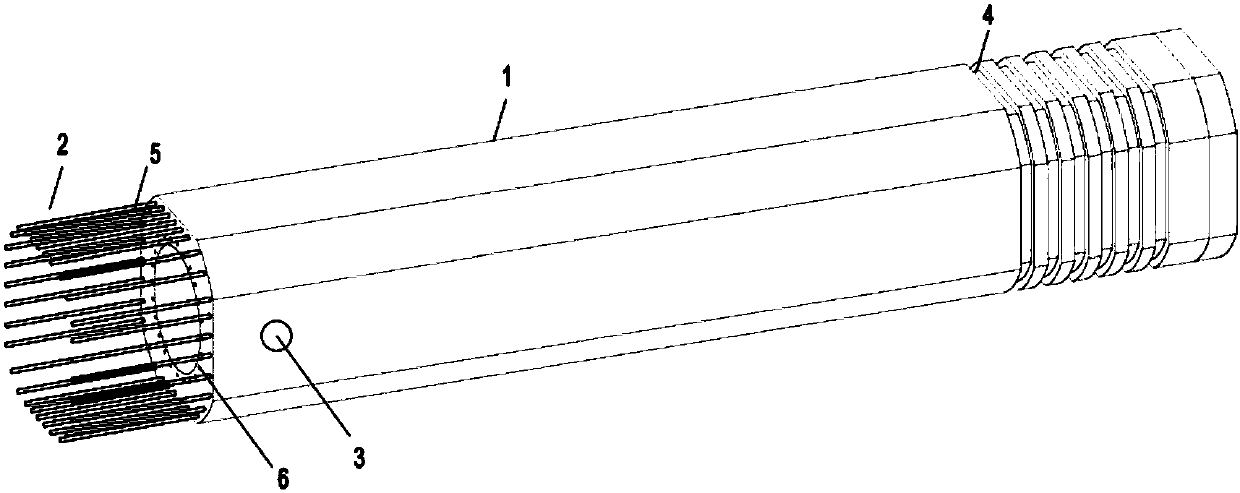
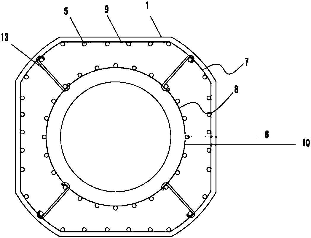
[0040] A kind of prefabricated high-strength concrete bridge pier of this embodiment, such as figure 1As shown, it includes pier body 1, steel frame cage 2 and hoisting hole 3. The pier body 1 is a full-length hollow structure. The cross-sectional shape of the pier body 1 is composed of four straight line segments and four arc segments. The arc segments are all on the same circumference, and the diameter of the circle is the length of the straight line segment. 1.5 to 2.5 times of that. Concave-convex groove segments 4 are arranged on the outer surface of the pier body 1 within 0.4 times of the pier length above the bottom end. The hoisting holes 3 are set within the range of 0.3 times the length of the pier body from the top of the pier, are arranged along the circumference of the pier body 1 and run through the pier body 1, and there are ...


PUM

PropertyMeasurementUnit
Thread lengthaaaaaaaaaa

Abstract

The invention discloses a prefabricated high-strength concrete pier as well as a forming mold and a manufacturing method thereof. The bridge pier includes a pier body, a steel skeleton cage and a hoisting hole. The cross-sectional outer contour shape of the pier body is composed of more than four straight line segments and more than four arc segments, and all arc segments are located on the same circumference; The outer surface of the bottom of the pier is provided with concave-convex grooves; the hoisting holes are arranged along the circumference of the pier body and run through the pier body; there are more than two layers of steel skeleton cages inside the pier body, and the outermost layer of steel skeleton cages is shaped. On the inner side of the stirrup, the head end of the main bar is provided with a thread, and the tail end is provided with a sleeve with internal thread; the steel skeleton cage of the other layers is circular, and the main bar is arranged on the outside of the stirrup, and the head end and the tail end of the main bar are both There is a sleeve with internal thread; the steel skeleton cages of two adjacent layers are connected by connecting pieces. The prefabricated concrete pier of the invention has the advantages of excellent mechanical properties, high concrete strength grade, simple and convenient production process, and the like.

Description

technical field [0001] The invention relates to the technical field of building bridges, and relates to an improvement in the shape and structure of a bridge pier, a molding die for the bridge pier and a manufacturing method for the bridge pier. Specifically, it is a prefabricated high-strength concrete bridge pier and its forming mold and manufacturing method. Background technique [0002] Most of the viaduct piers in highways and municipal roads are cast-in-place. Concrete piers poured on site are greatly affected by the site environment. For example, construction in rainy days cannot guarantee the quality and construction period of bridge piers in urban elevated areas, and will also cause certain damage to the surrounding environment. In addition, since the cast-in-place bridge piers are directly filled with concrete into the prefabricated steel bars at the construction site and formed after natural curing, there are many factors affecting the strength of the concrete. ...

Claims


Application Information

Patent Timeline
IPC IPC(8): B28B7/18B28B7/00B28B23/10B28B23/12B28B11/24E01D19/02E01D101/28
CPCE01D19/02B28B7/0002B28B7/18B28B11/245B28B23/10B28B23/12E01D2101/28
Inventor 毛由田毛永平李志高马进元姚栋安雄飞陈巧王卫民
Owner JIANHUA CONSTR MATERIALS (CHINA) CO LTD
Why Eureka
Try Eureka