Preparation apparatus for combustible gas

A gas preparation and equipment technology, applied in the field of combustible gas preparation equipment, can solve the problems of inconvenient recovery and cleaning, inability to ensure methane concentration, low secondary utilization rate of waste, etc. The effect of high utilization rate and high degree of automation

Inactive Publication Date: 2018-04-20
鄢碧珠
View PDF0 Cites 3 Cited by
  • Summary
  • Abstract
  • Description
  • Claims
  • Application Information

AI Technical Summary

Problems solved by technology

[0002] Biogas is a combustible gas produced by microbial fermentation of organic matter in an anaerobic environment under certain temperature, humidity, and pH conditions. Biogas is more and more widely used in rural areas, and there are many biogas pits for biogas production. There are various types. When the existing biogas digesters process the fermented waste, most of them use single-channel recycling to recycle the waste, which cannot separate the waste liquid and waste residue in the waste. Not only is it inconvenient to recycle and clean up, but also the waste The secondary utilization rate is also low, and when the existing biogas digesters collect biogas, they cannot monitor the concentration of biogas, and cannot ensure that the methane concentration in the collected biogas can meet the collection standards. At the same time, the existing biogas digesters Lack of corresponding pretreatment equipment, the raw materials cannot be crushed, so that the raw materials cannot be completely fermented, and the energy utilization rate is low. Therefore, the research and development of new multi-channel processing biogas digesters has attracted more and more attention from researchers.

Method used


Image

  • Preparation apparatus for combustible gas
  • Preparation apparatus for combustible gas
  • Preparation apparatus for combustible gas

Examples


Embodiment Construction

[0015] The following will clearly and completely describe the technical solutions in the embodiments of the present invention with reference to the accompanying drawings in the embodiments of the present invention. Obviously, the described embodiments are only some, not all, embodiments of the present invention. Based on the embodiments of the present invention, all other embodiments obtained by persons of ordinary skill in the art without making creative efforts belong to the protection scope of the present invention.

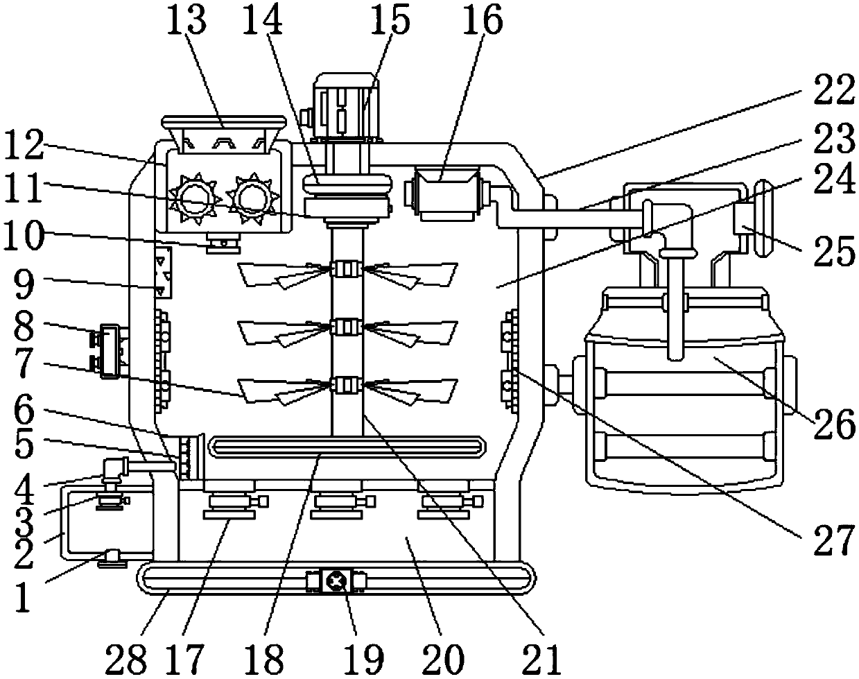
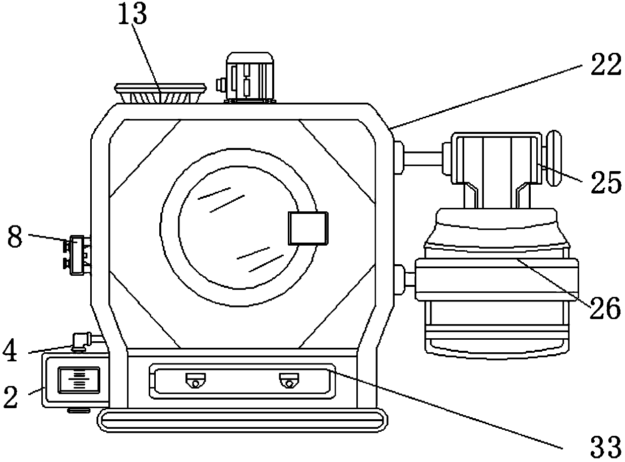
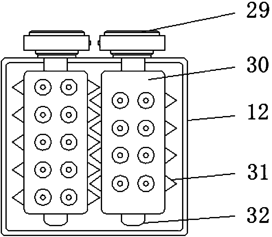
[0016] see Figure 1-3 , an embodiment provided by the present invention: a combustible gas preparation equipment, including a waste liquid tank 2, a crushing bin 12, a pool body 22, a fermentation bin 24 and a gas storage tank 26, and a bottom plate 28 is installed below the pool body 22 , and a single-chip microcomputer 19 is installed at the middle position below the inside of the bottom plate 28, where the single-chip microcomputer 19 can be an AT89C51 sin...


PUM


Abstract

The invention discloses a preparation apparatus for combustible gas. The preparation apparatus comprises a waste liquid case, a crushing cabin, a pool body, a fermentation cabin and a gas storage tank, wherein a base plate is mounted below the pool body; a single-chip microcomputer is arranged at the central position of the interior lower part of the base plate; the fermentation cabin is arrangedin and located at the upper part of the pool body; a waste residue cabin is arranged in and located at the lower part of the pool body; one side of the pool body is provided with the gas storage tank;and the waste liquid case is arranged below one side, away from the gas storage tank, of the pool body. The preparation apparatus provided by the invention is provided with the waste liquid case, thewaste residue cabin, a filter tube, a pneumatic cylinder and a pressure plate; the pneumatic cylinder presses a waste material via the pressure plate and can extrude waste liquid out from the waste material; the filter tube can filter out water in the waste material; and waste liquid and waste residues are respectively stored in the waste liquid case and the waste residue cabin in a multichanneltreatment manner. Thus, classified collection and cleaning of the waste material are facilitated; and since the waste liquid can be used for fertilization of crops, the secondary utilization rate of the waste material is increased.

Description

technical field [0001] The invention relates to the technical field of biogas preparation equipment, in particular to a combustible gas preparation equipment. Background technique [0002] Biogas is a combustible gas produced by microbial fermentation of organic matter in an anaerobic environment under certain temperature, humidity, and pH conditions. Biogas is more and more widely used in rural areas, and there are many biogas pits for biogas production. There are various types. When the existing biogas digesters process the fermented waste, most of them use single-channel recycling to recycle the waste, which cannot separate the waste liquid and waste residue in the waste. Not only is it inconvenient to recycle and clean up, but also the waste The secondary utilization rate is also low, and when the existing biogas digesters collect biogas, they cannot monitor the concentration of biogas, and cannot ensure that the methane concentration in the collected biogas can meet the...

Claims


Application Information

Patent Timeline
Patent Type & Authority Applications(China)
IPC IPC(8): C12M1/107C12M1/34C12M1/36C12M1/12C12M1/00
CPCC12M21/04C12M29/04C12M41/34C12M41/48C12M45/02
Inventor 鄢碧珠
Owner 鄢碧珠
Why Eureka
Try Eureka