Efficient cable shearing device for electric power

A cable device, high-efficiency technology, applied in the field of high-efficiency cable cutting device for electric power, can solve the problems of low work efficiency and low accuracy

Inactive Publication Date: 2021-05-18
纵凯旋
View PDF6 Cites 3 Cited by
  • Summary
  • Abstract
  • Description
  • Claims
  • Application Information

AI Technical Summary

Problems solved by technology

[0006] The purpose of the present invention is to provide a high-efficiency cable cutting device for electric power, which solves the problem that in the prior art, human power is used to cut through the cutting device, and the work efficiency is low and too tiring, and it is impossible to complete a large number of cuts and install it in the receiving direction. Unified collection and use, the length of the cable is also artificially estimated and cut, resulting in low accuracy and low work efficiency

Method used


Image

  • Efficient cable shearing device for electric power
  • Efficient cable shearing device for electric power
  • Efficient cable shearing device for electric power

Examples


Embodiment 1

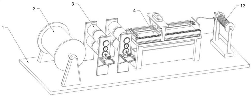
[0035] refer to Figure 1-4 , the loading plate 1 and the winding roller-2 on the top side of the loading plate 1, and the side of the winding roller-2 are parallelly provided with two pay-off auxiliary mechanisms 3, and the two pay-off auxiliary mechanisms 3 are far away from the winding roller-2 One side is provided with cutting device 4.

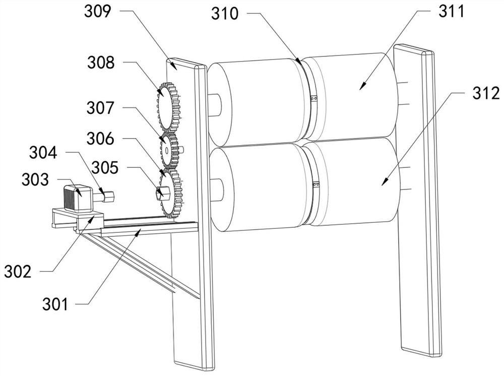
[0036] The two auxiliary wire release mechanisms 3 all include two vertical plates 309 fixedly connected to the top of the bearing plate 1 and two parallel rollers 311 and 312 arranged between the two vertical plates 309, the first roller 311 and the second roller 312. Roller shaft 2 312 is rotatably connected with two vertical plates 309 through a rotating shaft, and the middle of the outer ring of roller shaft 1 311 and roller shaft 2 312 is provided with a circular groove 310, and one side of one of the vertical plates 309 of the two vertical plates 309 Be provided with driven gear plate two 308 two, the bottom of driven gear plate tw...

Embodiment 2

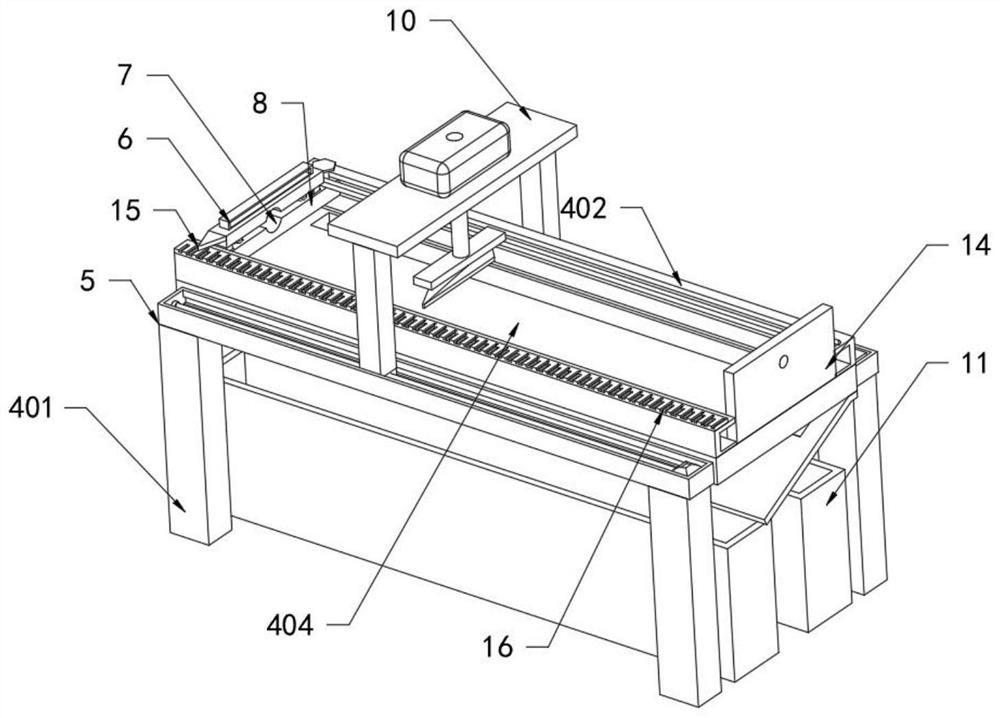
[0044] refer to figure 1 with Figure 6-7 , both sides of the top of the platen 404 are fixedly connected with a cross bar 402, a slide plate 8 is arranged between the two cross bars 402, the top of the slide plate 8 is elastically connected with a top plate 6 through two extrusion springs, and the top plate 6 and the slide plate 8 The corresponding side is provided with a semi-circular groove 7, the corresponding side of the two cross bars 402 is provided with a chute compatible with the slide plate 8, and the corresponding sides of the top plate 6 and the slide plate 8 are provided with a semi-circular groove 7 plays the role of guiding the cables, so that the cables can be placed on the platen 404 horizontally and without bending, which is convenient for cutting and improves operation efficiency.

[0045] A scale plate 16 is fixedly connected to the top of one of the two cross bars 402 , an arrow 15 is arranged on one side of the top of the scale plate 16 , and one side of...

Embodiment 3

[0050] refer to figure 1 with Figure 5 , the bottom of the platen 404 is provided with a collection mechanism 11, the collection mechanism 11 includes a collection bin one 1101 and a second collection bin 1102 fixedly connected to the top of the carrier plate 1 and a sorting plate 1103 fixedly connected to the bottom of the deck 404, the sorting plate 1103 and The angle of the platen 404 is 30°-50°, the corresponding side of the platen 404 and the sorting plate 1103 is provided with a notch 1104, and the notch 1104 of the sorting plate 1103 is equipped with an electric valve 1105, and the second collection bin 1102 It is arranged at the bottom of one side of the sorting plate 1103 , and the collection bin one 1101 is set at the bottom of the notch 1104 of the sorting plate 1103 .

[0051] Through the setting of the first collection bin 1101 and the second collection bin 1102, the sorting plate 1103, the notch 1104 and the electric valve 1105, the cut cable can fall on the so...


PUM


Abstract

The invention relates to the technical field of cable equipment, in particular to an efficient cable shearing device for electric power. The device solves the problems that in the prior art, manual cutting is carried out through a shearing device, the working efficiency is low and tiredness is caused, a large amount of cutting cannot be completed and then loaded in a material receiving direction for unified collection and use, the length of a cable is also manually estimated and sheared, the accuracy is low, and the working efficiency is relatively low. The efficient cable shearing device for the electric power comprises a bearing plate and a first winding roller on one side of the top of the bearing plate, two pay-off auxiliary mechanisms are arranged on one side of the first winding roller in parallel, and a cutting device is arranged on one sides, away from the first winding roller, of the two pay-off auxiliary mechanisms. According to the efficient cable shearing device, automatic shearing of cables can be conveniently achieved, the working efficiency is improved, the labor amount of workers is reduced, the shearing length accuracy is improved, the shearing quality is improved, the collecting efficiency is improved, and the time occupied by later classification is shortened.

Description

technical field [0001] The invention relates to the technical field of cable equipment, in particular to a high-efficiency cable cutting device for electric power. Background technique [0002] With the rapid development of modern cities, more and more cables are used in urban construction and modification projects, which are usually rope-like cables twisted by several or groups of wires (at least two in each group), each group of wires They are insulated from each other and are often twisted around a center. The entire outer surface is covered with a highly insulating covering. The cable has the characteristics of internal energization and external insulation. The cables currently used need to be cut before use. The traditional cutting cable The device is not perfect. [0003] 1. It is cut by manpower through the shearing device, the work efficiency is low and too tiring. [0004] 2. Unable to complete a large number of cuts and then install them in the receiving directio...

Claims


Application Information

Patent Timeline
Patent Type & Authority Applications(China)
IPC IPC(8): B21F11/00
CPCB21F11/00
Inventor 纵凯旋
Owner 纵凯旋
Why Eureka
Try Eureka