Ceramsite sand drying device

A drying device and ceramsite sand technology are applied in the directions of drying, drying machine, drying gas arrangement, etc., which can solve the problems of poor drying effect and uneven heating, prevent uneven heating, and facilitate classification and collection. The effect of subsequent use

Inactive Publication Date: 2020-06-09
江西达人建材有限公司
View PDF5 Cites 3 Cited by
  • Summary
  • Abstract
  • Description
  • Claims
  • Application Information

AI Technical Summary

Problems solved by technology

[0003] After the ceramsite sand is granulated, it generally needs to go through a drying process to ensure that the particles are not easy to break when calcined at high temperature in the calcination kiln. The existing ceramsite sand drying device cannot turn over the ceramsite sand during the baking process. Granular sand makes it heated unevenly, resulting in poor drying effect

Method used


Image

  • Ceramsite sand drying device
  • Ceramsite sand drying device
  • Ceramsite sand drying device

Examples


Embodiment 1

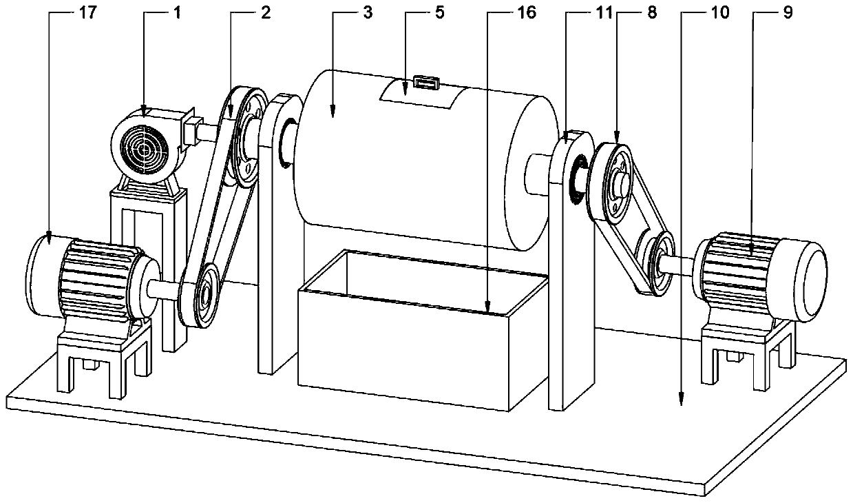
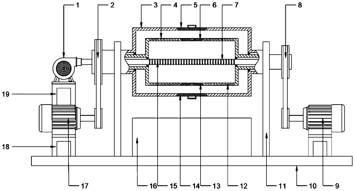
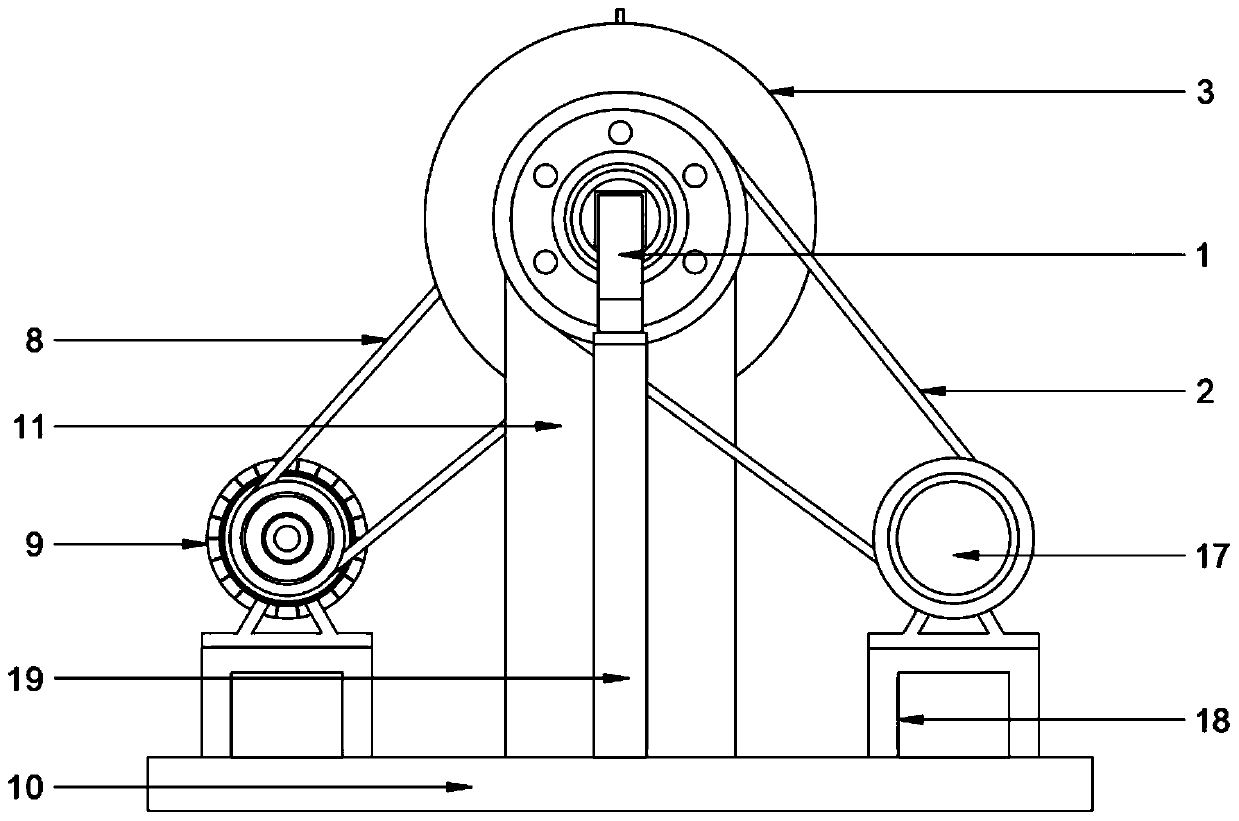
[0024] see Figure 1~4 , in an embodiment of the present invention, a ceramsite sand drying device includes a frame, a drum and a drying assembly installed on the frame, and the frame includes a bottom plate 10 and two groups of rollers fixedly arranged on the bottom plate 10 Support 11, the two ends of the drum are rotatably installed on the drum support 11, the upper and lower parts of the drum are respectively provided with a feed door and a discharge door, which are used for feeding and discharging respectively; one end of the drying assembly is provided It is at the axis position inside the drum and its other end passes through the drum and is fixedly connected with the fan support 19 fixedly arranged on the bottom plate 10; the power mechanism for driving the drum to rotate is also arranged on the frame.

[0025] Put the material into the drum through the feed door, close the feed door, start the power mechanism, and start the drying component at the same time, and use t...

Embodiment 2

[0032] see Figure 1~2 , in the embodiment of the present invention, a ceramsite sand drying device, in order to enhance the practicability of the device and facilitate the classification and collection of dried materials, on the basis of embodiment 1, the bottom plate 10 is still provided with storage Material box 16 and material storage box 16 are positioned at the first discharge door 14 below, and the quantity of described material storage box 16 is two groups; Open the first discharge door 14, the material in the first drum 3 is conveyed to a group of storage. In the material box 16, after collecting the materials in the first drum 3, replace another group of material storage boxes 16, open the second discharge door 13, and transport the materials in the second drum 4 to another group of material storage boxes 16 Inside, two groups of material storage boxes 16 are used to hold the materials in the first drum 3 and the second drum 4 respectively, which is convenient for cl...


PUM


Abstract

The invention discloses a ceramsite sand drying device. The ceramsite sand drying device comprises a rack, a roller and a drying assembly, the roller and the drying assembly are installed on the rack,the rack comprises a bottom plate and two sets of roller supports fixedly arranged on the bottom plate, the two ends of the roller are rotationally installed on the roller supports, and a feeding door and a discharging door are arranged on the upper portion and the lower portion of the roller correspondingly; one end of the drying assembly is arranged at the axis position in the roller, and the other end of the drying assembly penetrates out of the roller to be fixedly connected with a fan support fixedly arranged on the bottom plate; and a power mechanism for driving the roller to rotate isfurther arranged on the rack. According to the ceramsite sand drying device, a fan and an air pipe are adopted, so that heat in the roller is uniformly distributed; a second roller with sieve holes isadopted, ceramsite sand with different particle sizes is screened out, and uneven heating is prevented; the first roller and the second roller rotate reversely, ceramsite sand is turned over, dryingis accelerated, and material accumulation and excessive baking by hot air are prevented; and two groups of discharge doors and two groups of storage boxes are adopted and output separately, so that classified collection is facilitated.

Description

technical field [0001] The invention relates to a drying device, in particular to a ceramsite sand drying device. Background technique [0002] Ceramsite sand is often used to replace crushed stones and pebbles in concrete because of its thermal insulation, low water absorption, good frost resistance and durability. Various raw materials such as clay, slate, shale, coal gangue, and industrial solid waste are sintered by ceramics. [0003] After the ceramsite sand is granulated, it generally needs to go through a drying process to ensure that the particles are not easy to break when calcined at high temperature in the calcination kiln. The existing ceramsite sand drying device cannot turn over the ceramsite sand during the baking process. Granular sand, so that it is heated unevenly, resulting in poor drying effect. Contents of the invention [0004] The object of the present invention is to provide a ceramsite sand drying device to solve the problems raised in the above-...

Claims


Application Information

Patent Timeline
IPC IPC(8): F26B11/04F26B25/16F26B25/02F26B21/00F26B25/00B07B1/22
CPCB07B1/22F26B11/022F26B11/0413F26B21/001F26B21/004F26B25/002F26B25/16F26B2200/08F26B2210/02
Inventor 胡宏龙洪慧珍洪磊
Owner 江西达人建材有限公司
Why Eureka
Try Eureka