System and method for producing sponge iron by gas-based shaft furnace

A gas-based shaft furnace and sponge iron technology, applied in shaft furnaces, furnaces, furnace types, etc., can solve the problems of long process flow, high requirements on raw material conditions, low heat release, etc., to shorten the process flow and shorten the reaction time. , the effect of increasing the smelting temperature

Pending Publication Date: 2018-04-20
JIANGSU PROVINCE METALLURGICAL DESIGN INST
View PDF0 Cites 0 Cited by
  • Summary
  • Abstract
  • Description
  • Claims
  • Application Information

AI Technical Summary

Problems solved by technology

This method mainly has the following problems: 1) CO reduction of iron oxide is an exothermic reaction, while H 2 The reduction of iron oxide is an endothermic reaction, increasing the temperature is not conducive to the utilization of CO gas, but it is beneficial to increase the H 2 The utilization rate of the gas, so the reaction requires strict control of temperature and reducing gas components in order to obtain the best reduction effect
2) This method needs to independently set up a reducing gas preparation device to obtain reducing gas, and the process is relatively long
3) The reducing gas required by the method is derived from natural gas, which reacts with water to obtain H 2 And CO, the reaction is an endothermic reaction, although the generated CO will release a certain amount of heat when it reacts with iron oxides, but the heat release is much lower than that of the corresponding CH 4 The heat released by full combustion will cause a certain amount of energy loss, and the utilization rate of natural gas is low
4) with CO and H 2 When it is reducing gas, in order to reduce the difficulty of reduction and increase the reduction rate, it uses oxidized pellets as raw material, which has high requirements on raw material conditions, and it is difficult to use iron concentrate powder green pellets or natural iron ore, which increases the energy consumption of oxidation roasting

Method used


Image

  • System and method for producing sponge iron by gas-based shaft furnace

Examples


Embodiment 1

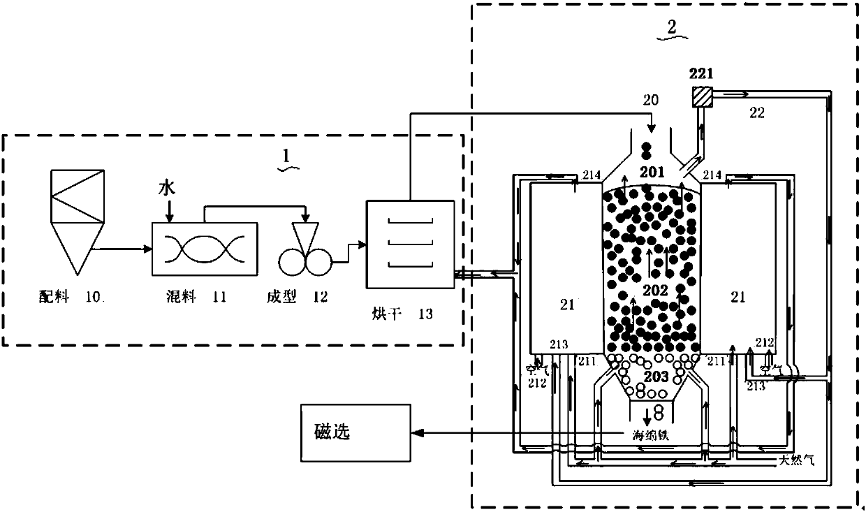
[0050] Add 5 parts of bentonite and 5 parts of water to 100 parts of hematite powder, mix them evenly, and then send them to a briquette machine for compacting to obtain green pellets with a particle size of 15-20mm. Put it into the drying device for drying, and dry for 2-3 hours, and the dry pellets after drying are sent to the air-based shaft furnace. Before the dry pellets are fed into the gas-based shaft furnace, natural gas and combustion-supporting air are introduced into the combustion chamber of the gas-based shaft furnace to heat the body of the gas-based shaft furnace. After the temperature in the reduction section is measured to be between 900°C and 1000°C, if In this embodiment, the temperature is 980°C, iron ore powder dry pellets are added from the feeding section, and natural gas is fed through the gas inlet at the bottom of the gas-based shaft furnace. After reacting for 20-30 minutes, open the top gas inlet of the combustion chamber, let the top gas and air wa...

Embodiment 2

[0052] Prepare 100 parts of hematite powder, mix with 3 parts of bentonite, 2 parts of starch and 8 parts of water, and then send it to a briquetting machine for pressing to form green pellets with a particle size of 15-20mm. The pellets are sent to the drying device for drying for 2-3 hours, and the dried pellets are sent to the air-based shaft furnace. Before the dry pellets are fed into the gas-based shaft furnace, natural gas and combustion-supporting air are introduced into the combustion chamber of the gas-based shaft furnace to heat the body of the gas-based shaft furnace. After the temperature in the reduction section is measured to be between 900°C and 1000°C, if In this embodiment, the temperature is 900°C, iron ore powder dry pellets are added from the feeding section, and natural gas is fed through the air inlet at the bottom of the gas-based shaft furnace. After reacting for 20-30 minutes, open the top gas inlet of the combustion chamber, let the top gas and air w...

Embodiment 3

[0054] Prepare 100 parts of hematite powder, mix with 4 parts of bentonite, 1 part of starch and 7 parts of water, and then send it to a briquetting machine for pressing to form green pellets with a particle size of 15-20mm. The pellets are sent to the drying device for drying for 2-3 hours, and the dried pellets are sent to the air-based shaft furnace. Before the dry pellets are fed into the gas-based shaft furnace, natural gas and combustion-supporting air are introduced into the combustion chamber of the gas-based shaft furnace to heat the body of the gas-based shaft furnace. After the temperature in the reduction section is measured to be between 900°C and 1000°C, if In this embodiment, the temperature is 1000°C, iron ore powder dry pellets are added from the feeding section, and natural gas is fed through the air inlet at the bottom of the gas-based shaft furnace. After reacting for 20-30 minutes, open the top gas inlet of the combustion chamber, let the top gas and air w...


PUM

PropertyMeasurementUnit
particle sizeaaaaaaaaaa

Abstract

The invention relates to a system and method for producing sponge iron by a gas-based shaft furnace. The system for producing the sponge iron by the gas-based shaft furnace comprises a raw material pre-treatment system and the gas-based shaft furnace which are sequentially arranged, wherein the raw material pre-treatment system comprises a forming device; the gas-based shaft furnace comprises a furnace body, a combustion chamber and a top gas utilizing system; the furnace body sequentially comprises a charging section, a reduction section and a cooling section from top to bottom; and the combustion chamber is arranged outside the reduction section, a top gas outlet is formed in one side of the charging section, the top gas outlet is connected with a gas inlet of a washing tower of the topgas utilizing system, an outlet of the washing tower is connected with a top gas inlet of the combustion chamber, and a gas inlet is formed in the cooling section. The system and method for producingthe sponge iron by the gas-based shaft furnace shorten a technology process that iron is prepared and reduced directly through a shaft furnace method, lower the technology control difficulty, shortenthe reaction time, reduce energy losses, and improve the adaptation of the raw materials.

Description

technical field [0001] The invention relates to the technical field of gas-based shaft furnaces, in particular to a system and method for producing sponge iron in a gas-based shaft furnace. Background technique [0002] Sponge iron, also known as direct reduced iron, is a low-carbon porous substance formed by fine iron powder or iron oxide in a furnace through low-temperature reduction. It is mainly used as a raw material for electric furnace steelmaking, and can also be used as a coolant for converter steelmaking. An essential high-grade raw material for steel. [0003] At present, the main production method of direct reduced iron in the world is the shaft furnace method with natural gas as the energy source, which uses CO and H 2 The main high-temperature reducing gas is used as the reducing agent, and the direct reduced iron is produced in the shaft furnace by external or internal heating. The method mainly includes forming iron concentrate powder, oxidizing and roastin...

Claims


Application Information

Patent Timeline
Patent Type & Authority Applications(China)
IPC IPC(8): C21B13/02
CPCY02P10/143C21B13/02C21B13/0073
Inventor 陈佩仙任中山闫方兴郑常乐徐刚曹志成吴道洪
Owner JIANGSU PROVINCE METALLURGICAL DESIGN INST
Why Eureka
Try Eureka