
Portable duct water current power generator

A generator, portable technology, applied in the directions of hydroelectric power generation, current collectors, reaction engines, etc., can solve the problems of difficulty in meeting the demand for electricity in the field, damage to swimming organisms, short service life, etc., to achieve high-efficiency power generation and improve water flow. energy, the effect of improving power generation efficiency

Pending Publication Date: 2018-04-20
长沙紫宸科技开发有限公司
View PDF6 Cites 0 Cited by
  • Summary
  • Abstract
  • Description
  • Claims
  • Application Information

AI Technical Summary

Problems solved by technology

The equipment has the following obvious deficiencies: first, it adopts a floating mechanism, trying to directly use the natural water flow in the lower layer to impact the impeller, which requires specific field water flow conditions and the generated electricity is extremely small, which is difficult to meet the demand for field power consumption; Suspension equipment has the problem of fixing the equipment, and the airbag structure itself has certain hidden dangers, and its service life is short; third, it may also cause harm to wild aquatic organisms, and it is easy to be blocked by branches, aquatic plants or organisms in the wild water flow Card

Method used


Image

  • Portable duct water current power generator
  • Portable duct water current power generator
  • Portable duct water current power generator

Examples


Embodiment 1

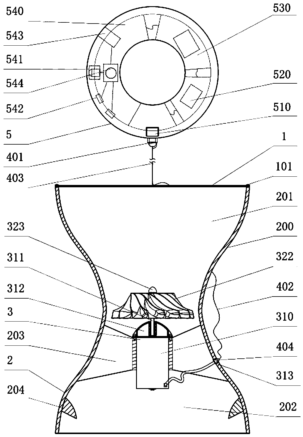
[0037] Such as figure 1 As shown, a portable ducted water flow generator mainly includes an anti-blocking device 1, a catchment ducting device 2, a power generation device 3, a cable 4 and a distribution and power supply device 5;

[0038] The anti-blocking device 1 is a grid plate, and the grid plate can be a synthetic rubber plastic grid plate; the anti-blocking device 1 can not only be used to prevent branches, rattan, sand and stones from blocking the culvert under field conditions. The power generating device 3 can also be used to prevent aquatic organisms entering the duct from being injured. The anti-jamming device 1 is connected with the inlet 201 of the water collection channel device 2 through a buckle 101 . The water collection channel device 2 includes a cylinder body 200, one end of the cylinder body 200 is the water collection end inlet 201, the other end of the cylinder body 200 is the water distribution end outlet 202, and the middle part of the cylinder body ...

Embodiment 2

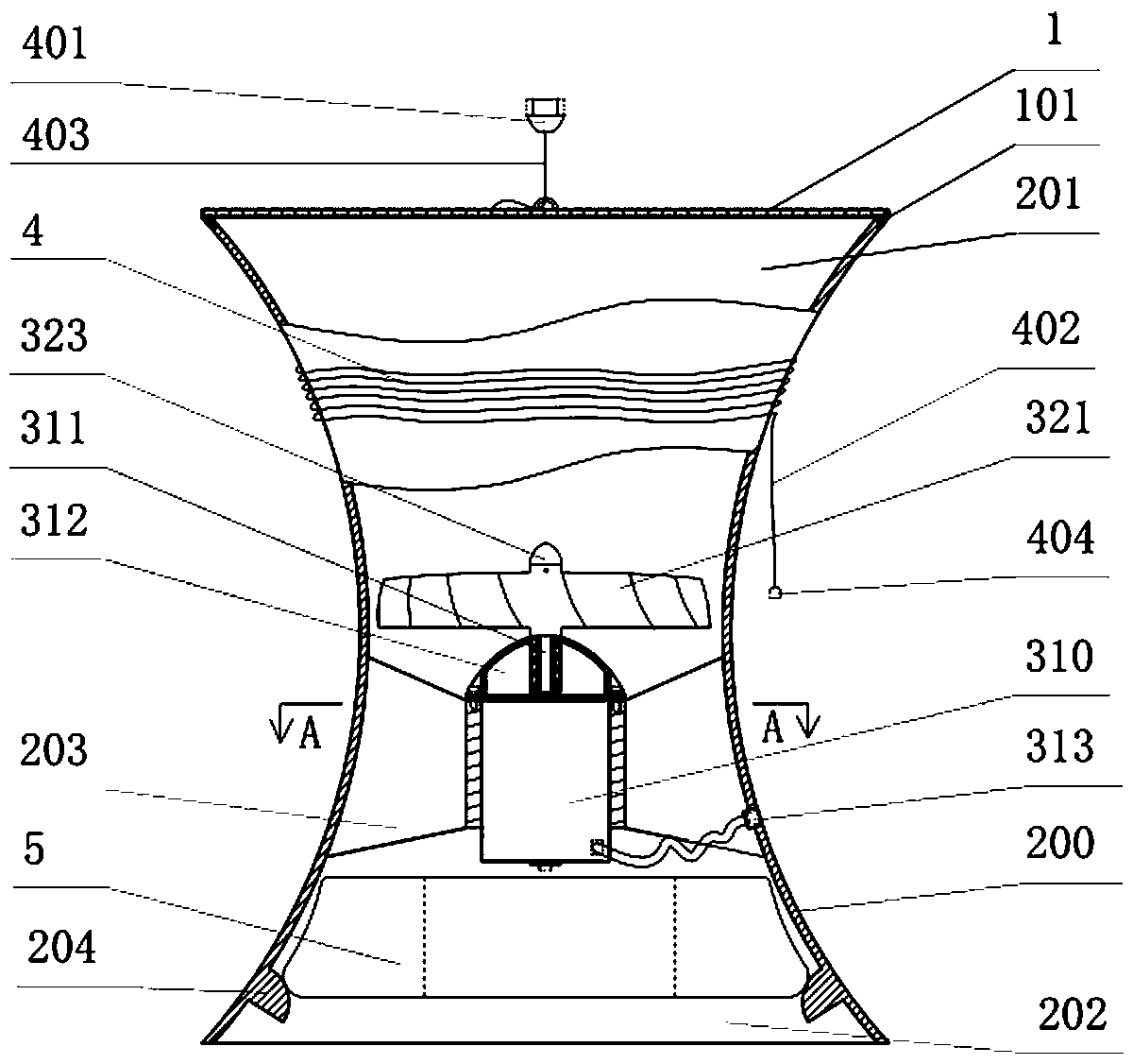
[0042] Such as diagram 2-1 and 2-2 As shown in the figure, a portable ducted water flow generator in a portable state mainly includes an anti-jamming device 1, a catchment ducting device 2, a power generation device 3, a cable 4 and a distribution and power supply device 5;

[0043] The anti-jamming device 1 is an alloy wire mesh; the anti-jamming device 1 can not only be used to prevent branches, vines, and sandstones from blocking the culvert and jam the power generation device 3 in the running water under field conditions, but also can be used to prevent the culvert from entering the culvert. Aquatic creatures are injured. The anti-jamming device 1 is connected with the inlet 201 of the water collection channel device 2 through a buckle 101 . The water collection channel device 2 includes a cylinder body 200, one end of the cylinder body 200 is the water collection end inlet 201, the other end of the cylinder body 200 is the water distribution end outlet 202, and the mid...

Embodiment 3

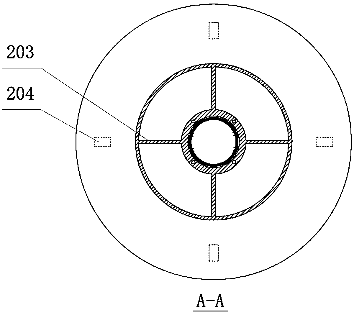
[0046] Such as image 3 As shown, a portable ducted water flow generator mainly includes an anti-blocking device 1, a catchment ducting device 2, a power generation device 3, a cable 4 and a distribution and power supply device 5;

[0047] The anti-jamming device 1 is a fiber screen; the anti-jamming device 1 can not only be used to prevent branches, vines, sandstones in the running water from blocking the duct and block the power generation device 3 under field conditions, but also can be used to prevent the power generation device 3 from entering the duct. Aquatic creatures are injured. The anti-jamming device 1 is connected to the inlet 201 of the water collection channel device 2 through bolts 102 . The water collection channel device 2 includes a cylinder body 200, one end of the cylinder body 200 is the water collection end inlet 201, the other end of the cylinder body 200 is the water distribution end outlet 202, and the middle part of the cylinder body 200 is provided...


PUM


Abstract

A portable duct water current power generator comprises an antiblocking device, a water converging duct device, a power generation device, a cable and a power distribution and supply device. The antiblocking device is connected to an inlet end of the water converging duct device, and the power generation device is fixed in the water converging duct device; the cable comprises an electric cable, one end of the electric cable is connected to the output wiring port of a power generator, and the other end of the electric cable is connected to an input interface of the power distribution and supplydevice; the power distribution and supply device comprises the input interface, a power transformation module, an electric power storage module and a functional module; and the functional module comprises a USB power supply interface, an LED lighting lamp, an igniter and a power supply switch. The USB power supply interface, the LED lighting lamp and the igniter are connected to the electric power storage module by the power supply switch. The portable duct water current power generator is suitable for the condition of field complex water currents and can prevent blockage and protect the creature in water, any field flowing water can be converged and accelerated, and the portable duct water current power generator can generate power efficiently without changing ecological environment andaffecting ecological conditions, realizes multiple purposes by one device, meets the outdoor life and outdoor exploration or working requirements of modern people, and is favorable for environment friendliness.

Description

technical field [0001] The invention relates to the technical field of new energy, in particular to a portable ducted water flow generator. Background technique [0002] Modern people's life and work are inseparable from electrical appliances, and in the case of outdoor activities such as expeditions, field survival, geological exploration, emergency rescue, earthquake floods, individual combat, etc., electrical appliances such as mobile phones, computers, lighting or drones use electricity Even wild ignition is often extremely inconvenient due to lack of electricity, which makes mobile energy storage devices become standard equipment for people to travel or work in the field. However, the capacity of existing portable mobile energy storage devices is limited, it is difficult to last for a long time, and it cannot meet the needs of the field. Electricity is used for continuous lighting and ignition in humid environments, and the existing power generation equipment is too lar...

Claims


Application Information

Patent Timeline
Patent Type & Authority Applications(China)
IPC IPC(8): F03B13/00F03B3/16F03B11/08H02J7/32
CPCH02J7/32F03B3/16F03B11/08F03B13/00Y02E10/20F05B2220/20F05B2220/602F05B2240/372F05B2240/133
Inventor 尹小林赵海洋
Owner 长沙紫宸科技开发有限公司
Learn More