Coupling method and coupling structure of silicon optical chip
A technology of silicon optical chip and coupling structure, which is applied in the coupling of optical waveguide, light guide, optics, etc., can solve the problems of inapplicability, and achieve the effect of simple and compact structure, simplified coupling and packaging difficulty, and small size
- Summary
- Abstract
- Description
- Claims
- Application Information
AI Technical Summary
Problems solved by technology
Method used
Image
Examples
Embodiment 1
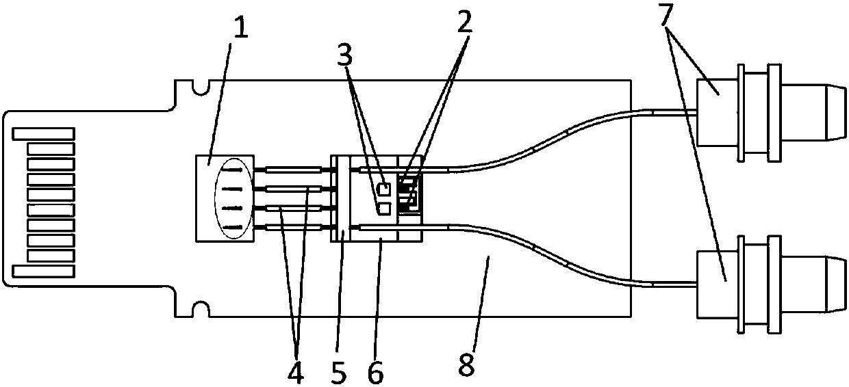
[0046] Embodiment 1 of the present invention provides a silicon optical chip coupling method, such as figure 1 As shown, the coupling structure includes an optical component, a silicon photonics chip 1 and a PCB board 8, wherein the optical component includes a laser chip 2, a coupling lens 3, an optical fiber 4, a glass cover 5, a V-groove substrate 6 and an external port 7, and the coupling method includes :
[0047] Bond and fix the silicon photonics chip 1 and the V-groove substrate 6 on the PCB board 8; place one end of the optical fiber 4 in the chip V-groove 1-1 on the coupling end surface of the silicon photonics chip 1, and place the other end of the optical fiber 4 In the V-groove 6-1 of the V-groove substrate 6;
[0048] Wherein, the laser chip 2 , the coupling lens 3 , the optical fiber 4 and the glass cover 5 are arranged on the V-groove substrate 6 .
[0049] Usually, the silicon photonic chip 1 also includes silicon waveguide coupling structures, couplers, mod...
Embodiment 2
[0061] The embodiment of the present invention also provides a coupling structure of a silicon photonics chip, the coupling structure includes an optical component, a silicon photonics chip 1 and a PCB board 8, wherein the optical component includes a laser chip 2, a coupling lens 3, an optical fiber 4, and a glass cover 5 , V-groove substrate 6 and external port 7, the coupling structure includes:
[0062] The silicon photonics chip 1 and the V-groove substrate 6 are bonded and fixed on the PCB board 8;
[0063] The optical fiber 4 is set in the chip V-groove 1-1 on the coupling end surface of the silicon photonics chip 1, and the other end is placed in the V-shaped groove 6-1 of the V-groove substrate 6;
[0064] Wherein, the laser chip 2 , the coupling lens 3 , the optical fiber 4 and the glass cover 5 are arranged on the V-groove substrate 6 .
[0065] The silicon photonics chip adopted in the embodiment of the present invention has an end-face coupling structure, and the...
Embodiment 3
[0069] The present invention also sets forth a coupling structure of a silicon photonics chip in a relatively complete manner starting from an industrial realization mode. The entire coupling element such as Figure 5 As shown, it consists of optical components, silicon photonics chip 1, PCB board 8, glass spacer 9, ultraviolet glue 10 and matching liquid 11, wherein the optical component consists of laser chip 2, coupling lens 3, optical fiber 4, glass cover plate 5, V The slot substrate 6 and the LC Receptacle 7 are coupled and packaged.
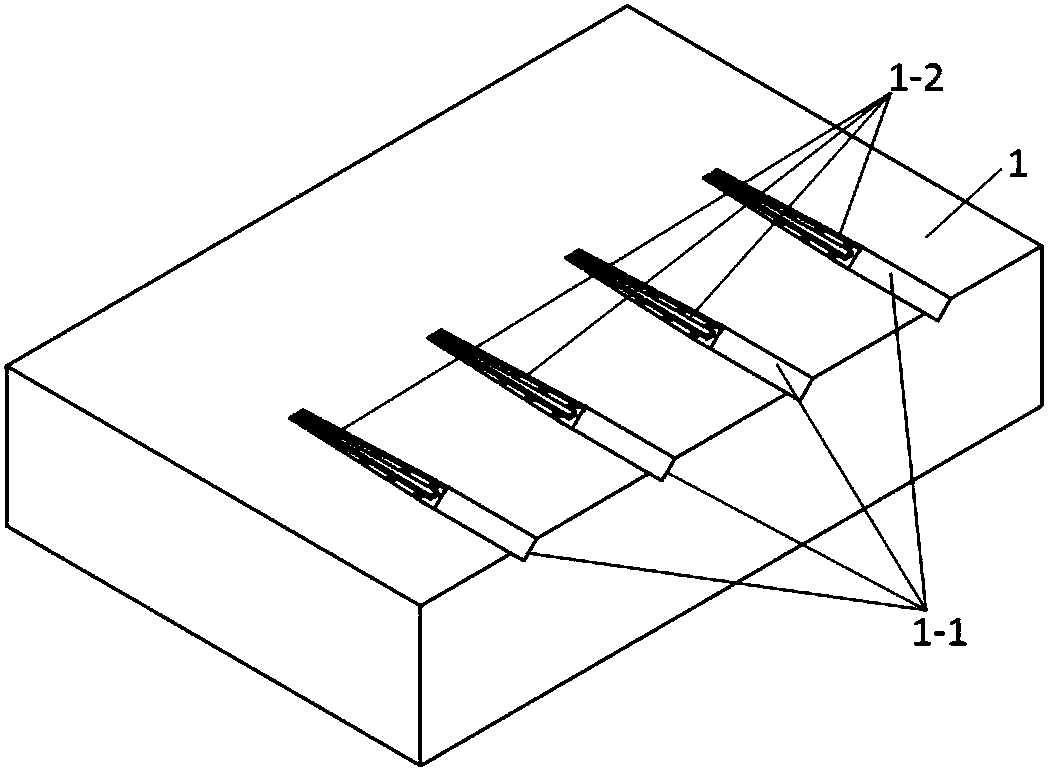
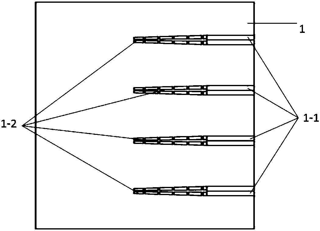
[0070] The silicon photonics chip 1 includes a silicon waveguide coupling structure, couplers, modulators, MPD, PD, TIA, laser drivers and other optoelectronic components. The chip coupling end surface is composed of a chip V groove 1-1 and a cantilever silicon waveguide 1-2. The silicon waveguide of the conventional silicon optical chip also adopts a cantilever design structure. The end face of the silicon waveguide is directly coupled w...
PUM
| Property | Measurement | Unit |
|---|---|---|
| Length | aaaaa | aaaaa |
Abstract
Description
Claims
Application Information
 - R&D
- Intellectual Property
- Life Sciences
- Materials
- Tech Scout
- Unparalleled Data Quality
- Higher Quality Content
- 60% Fewer Hallucinations
Browse by: Latest US Patents, China's latest patents, Technical Efficacy Thesaurus, Application Domain, Technology Topic, Popular Technical Reports.
© 2025 PatSnap. All rights reserved.Legal|Privacy policy|Modern Slavery Act Transparency Statement|Sitemap|About US| Contact US: help@patsnap.com


