Method for realizing truncated boundaries of anisotropic perfectly matched layers under Cartesian coordinate systems

A Cartesian coordinate system, fully matched layer technology, applied in the field of computational electromagnetism, can solve problems such as affecting computational efficiency, computational complexity, and narrow application range, and achieves the goal of overcoming low computational efficiency, improving computational efficiency, and improving computational efficiency. Effect

Active Publication Date: 2018-04-20
HEBEI UNIV OF TECH
View PDF6 Cites 5 Cited by
  • Summary
  • Abstract
  • Description
  • Claims
  • Application Information

AI Technical Summary

Problems solved by technology

Stephen D. Gendney proposed an anisotropic perfect matching layer in 1996, which can achieve a better absorption effect, but the inherent cubic grid makes the calculation area cube-shaped or square, which is wasted in the process of corner area and edge area processing. A lot of computer resources, and will cause unnecessary reflections
The Chinese patent No. 201210177288.0 discloses a method for realizing the complete absorption boundary of a two-dimensional cylindrical coordinate system, which omits the calculation of the edge area, but involves too many complicated mathematical expressions, which brings great difficulties to computer programming. difficulty
In addition, because the shape of its calculation area is cylindrical, the shape of the grid is also curved, and the size of the grid is proportional to the radius. Therefore, as the radius increases, the size of the outer grid will be larger, resulting in The calculation accuracy is greatly reduced, and the size of the grid may also exceed the limit of the "Courant stability condition", which leads to the instability of the algorithm
The Chinese patent application number 201410568490.5 discloses a truncated boundary of the impedance matching layer. The truncated boundary is truncated in the form of impedance matching. There are many parameters involved in this process, and the calculation is very complicated. Too many parameters will cause the computer program to become very redundant and affect the calculation efficiency. On the other hand, due to the inherent defects of the impedance matching layer, the applicable range is narrow and cannot meet the use requirements.
However, there is no implementation method to establish the anisotropy of the curved shape in the Cartesian coordinate system to perfectly match the layer truncation boundary

Method used


Image

  • Method for realizing truncated boundaries of anisotropic perfectly matched layers under Cartesian coordinate systems
  • Method for realizing truncated boundaries of anisotropic perfectly matched layers under Cartesian coordinate systems
  • Method for realizing truncated boundaries of anisotropic perfectly matched layers under Cartesian coordinate systems

Examples


Embodiment 1

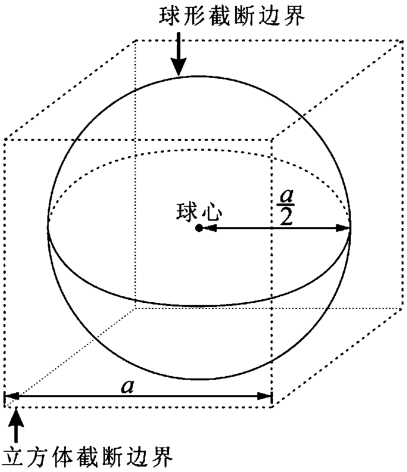
[0091] The implementation method of the truncated boundary of the anisotropic perfect matching layer in the Cartesian coordinate system in this embodiment is applied to the three-dimensional problem, and the shape of the truncated boundary of the anisotropic perfect matching layer is spherical. At this time, the steps of the method are as follows:

[0092] 1. Establish the model data of the solution object and the calculation space of the time domain finite difference method;

[0093] Apply for memory space from the computer, and the overall calculation range is (X n ,Y n ,Z n )→(Xp,Y p ,Z p ), whose size is (X p –X n )×(Y p –Y n )×(Z p -Z n ), where X n =Y n = Z n , X p =Y p = Z p , the spatial steps in the x, y, and z directions are Δx, Δy, and Δz, respectively, and Δx=Δy=Δz, the calculation area within the truncated boundary is a vacuum state, and the current source of the time-harmonic field is selected as the excitation of the three-dimensional problem sou...

Embodiment 2

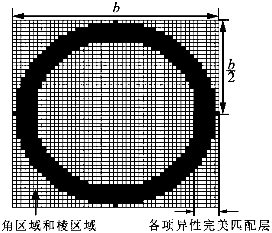
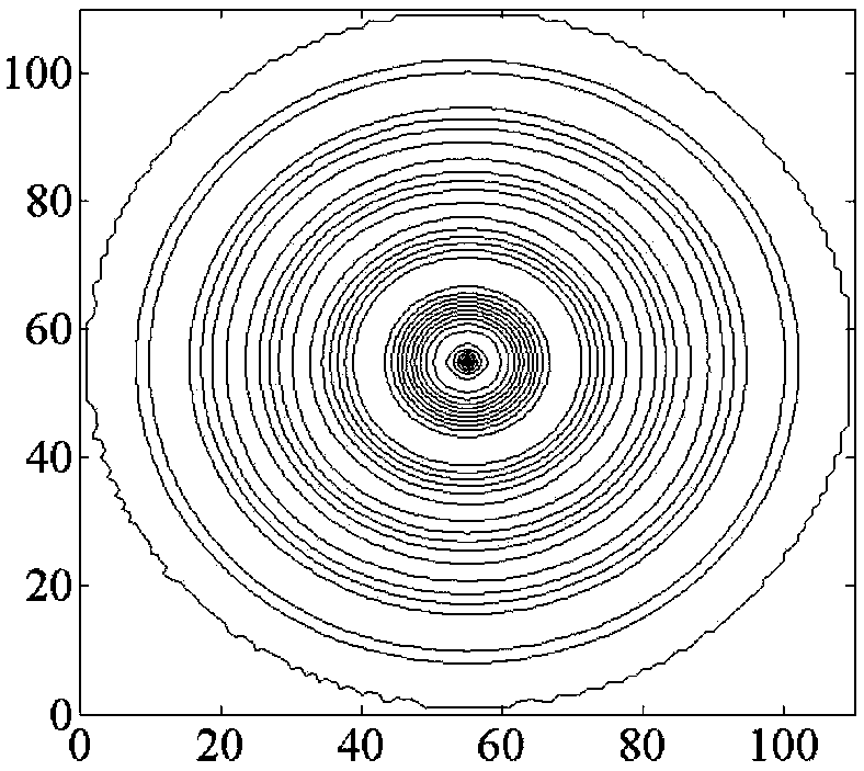
[0128] The steps of the implementation method in this embodiment are the same as those in Embodiment 1, the difference is that this embodiment is applied to the two-dimensional case, Δz is 0, and the truncation boundary of the anisotropic perfect matching layer is a circle, to verify the anisotropy in the two-dimensional case The absorbing effect of the implementation method that exactly matches the layer truncation boundary. The size of the calculation area is set to 110×110, the space step is Δx=Δy=1mm, the time step is Δt=16.667ps, the entire calculation area is in a vacuum state, its electrical conductivity is σ=0, and its magnetic permeability is mu 0 , with a dielectric constant ε 0 . The sinusoidal point source of the time harmonic field is selected as the excitation source, and the expression is E inc =sin(2πf 0 NΔt), f 0 is the frequency of the source, and the number of iteration steps of the electromagnetic simulation is N=1000. Run the program thus, the result...

Embodiment 3

[0130] The realization method of this embodiment is applied to the three-dimensional situation, and the steps of the specific realization method are the same as those in Embodiment 1, and the absorption effect of the realization method of the truncation boundary of an anisotropic perfectly matched layer in the Cartesian coordinate system described in the three-dimensional situation is verified. The size of the calculation area is set to 62×62×62, the space step is Δx=Δy=Δz=2mm, the time step is Δt=3.333ps, the electrical conductivity of the calculation area is σ=0, and the magnetic permeability is μ 0 , with a dielectric constant ε 0 . Add an electric dipole at the coordinate point (30,30,30), select the current source as the excitation source, and the expression is E inc =J 0 ×(t-t 0 )×exp(-(t-t 0 ) 2 / τ 2 ), the number of iteration steps of the electromagnetic simulation is N=1000. Thus run the program and record the electric field intensity E at the coordinate point ...


PUM


Abstract

The invention relates to a method for realizing truncated boundaries of anisotropic perfectly matched layers under Cartesian coordinate systems. The method is established under a Cartesian coordinatesystem, appearances of anisotropic perfectly matched layers in three-dimensional problems are spheres, and appearances of anisotropic perfectly matched layers in two-dimensional problems are circles,so that the sizes of grids are consistent, instable factors do not occur, residual grids can be truncated, the calculated amount is decreased, the calculation efficiency is improved, and the problem that square anisotropic perfectly matched layers under existing Cartesian coordinate system are low in calculation efficiency and complicated in calculation; and the appearances of the spheres are combined with square grids, so that stability and high efficiency are provided. Through a formula (as shown in the specification), parameters of truncated parameters of spherical anisotropic perfectly matched layers are designed to be used in programs of computational electromagnetics, so that the effect of simulating anechoic chamber wave-absorbing materials in limited calculation areas can be realized.

Description

technical field [0001] The invention belongs to the technical field of computational electromagnetics, and in particular relates to a method for realizing the truncation boundary of an anisotropic complete matching layer in a Cartesian coordinate system. Background technique [0002] The numerical calculation method of electromagnetic field is widely used in the research of microwave circuit, antenna design, target scattering calculation and electromagnetic compatibility, among which the finite difference time domain method is one of the most commonly used methods. For computer programming to solve electromagnetic field problems, limited memory cannot simulate an infinite calculation area. Therefore, it is necessary to set an absorbing layer on the edge of the calculation area as a truncated boundary so that electromagnetic waves are absorbed on the boundary. Its performance is comparable to the accuracy and accuracy of electromagnetic field numerical calculation. Efficiency...

Claims


Application Information

Patent Timeline
Patent Type & Authority Applications(China)
IPC IPC(8): G06F19/00
CPCG16Z99/00
Inventor 郑宏兴王辂张玉贤崔文杰王蒙军李尔平
Owner HEBEI UNIV OF TECH
Why Eureka
Try Eureka