Input-series-output-parallel (ISOP) system having natural voltage sharing characteristic and control method thereof
A control method and natural technology, applied in the ISOP system and its control field, can solve problems such as poor pressure equalization effect, and achieve the effect of simplifying the design method, improving the utilization rate, and improving the pressure equalizing effect and the current equalizing effect.
- Summary
- Abstract
- Description
- Claims
- Application Information
AI Technical Summary
Problems solved by technology
Method used
Image
Examples
Embodiment 1
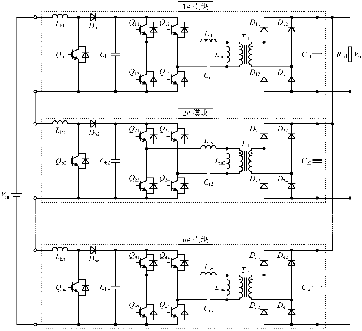
[0046] figure 1 , figure 2 It is the circuit schematic diagram of the ISOP system composed of n sub-modules and its control method, in which the input side of the Boost converter is connected in series, and the output side of the LLC resonant converter is connected in parallel.
example 2
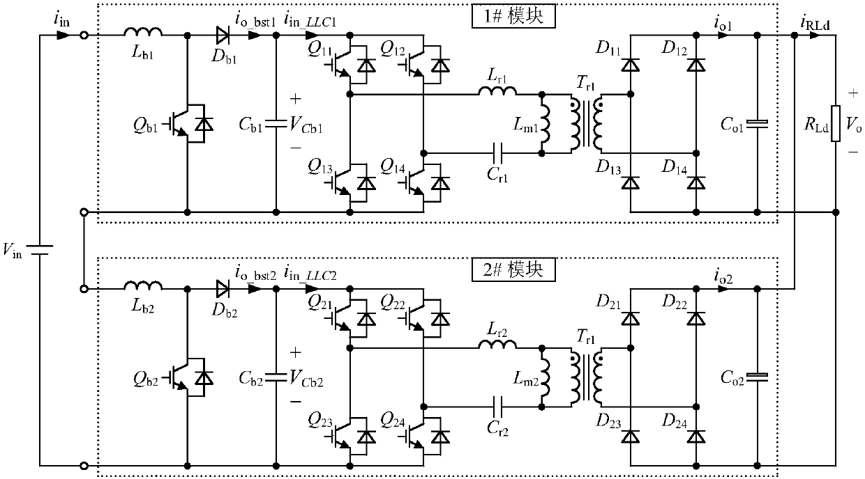
[0048] The following describes an ISOP system containing two Boost+LLC resonant converter modules as an example:
[0049] The ISOP system of this embodiment includes two Boost+LLC resonant converter modules. The two modules are connected in series at the input side and parallel at the output side. The design parameters of the two LLC resonant converters in the system are the same, and the design parameters of the two Boost converters are the same. Such as image 3 with Figure 4 Shown is an ISOP system with natural pressure and current equalization characteristics and its control method, including the following steps:
[0050] Step S1: Generate a duty cycle signal with a fixed frequency and pulse width through the DSP, and use it to control the LLC resonant converter after passing through the driving circuit. In each LLC resonant converter, the two pairs of switch tubes at diagonal angles are turned on and off at the same time, and the upper and lower tubes of the same bridg...
Embodiment 3
[0070] The second embodiment is based on the above-mentioned ISOP system, and a design method and experimental results of an application example are given below. The instance input voltage V in 1000V~2000V, output voltage V o is 700V, output power P o It is 12kW, and its detailed design steps are as follows:
[0071] 1) Design of Boost boost inductor
[0072] For a single Boost converter, its input voltage V in_bst It is half of the system input voltage, that is, 500V ~ 1000V, and its minimum value is V in_bstmin =500V. Therefore, considering the selection of the switching tube and the efficiency of the converter, the output voltage V of the Boost converter is selected Cb Slightly higher than the maximum input voltage, which is 1200V, the boost inductor is calculated according to the following formula,
[0073]
[0074] Among them, f sb is the switching frequency of the Boost converter, where 10kHz is taken, and P o_bst For the output power of a single Boost conver...
PUM
 Abstract
Description
Claims
Application Information
 - R&D
- Intellectual Property
- Life Sciences
- Materials
- Tech Scout
- Unparalleled Data Quality
- Higher Quality Content
- 60% Fewer Hallucinations
Browse by: Latest US Patents, China's latest patents, Technical Efficacy Thesaurus, Application Domain, Technology Topic, Popular Technical Reports.
© 2025 PatSnap. All rights reserved.Legal|Privacy policy|Modern Slavery Act Transparency Statement|Sitemap|About US| Contact US: help@patsnap.com


