Sewing machine foot pressing and lifting device

A presser foot lifter and sewing machine technology, applied in the field of sewing machine presser foot lifter, can solve problems such as the inability to adjust the height of the presser foot, achieve the effect of increasing the adjustment space and improving the service life

Active Publication Date: 2018-04-24
台州市速普机电有限公司
View PDF10 Cites 1 Cited by
  • Summary
  • Abstract
  • Description
  • Claims
  • Application Information

AI Technical Summary

Problems solved by technology

[0004]Some skilled mechanic can adjust the ordinary interlock sewing machine to about 7-9mm, but the interlock sewing machine with automatic thread trimming is limited The stroke limit of the wire electromagnet cannot be adjusted to the height of the presser foot that meets the process requirements

Method used


Image

  • Sewing machine foot pressing and lifting device
  • Sewing machine foot pressing and lifting device
  • Sewing machine foot pressing and lifting device

Examples


Embodiment 1

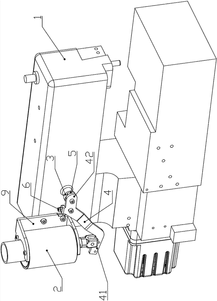
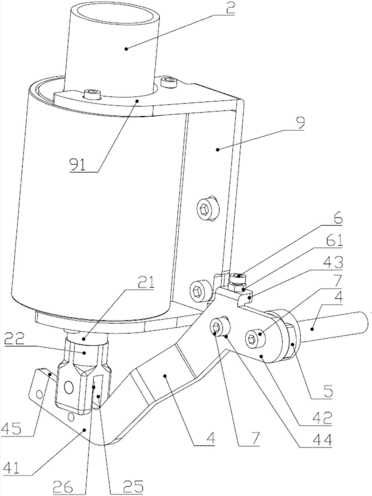
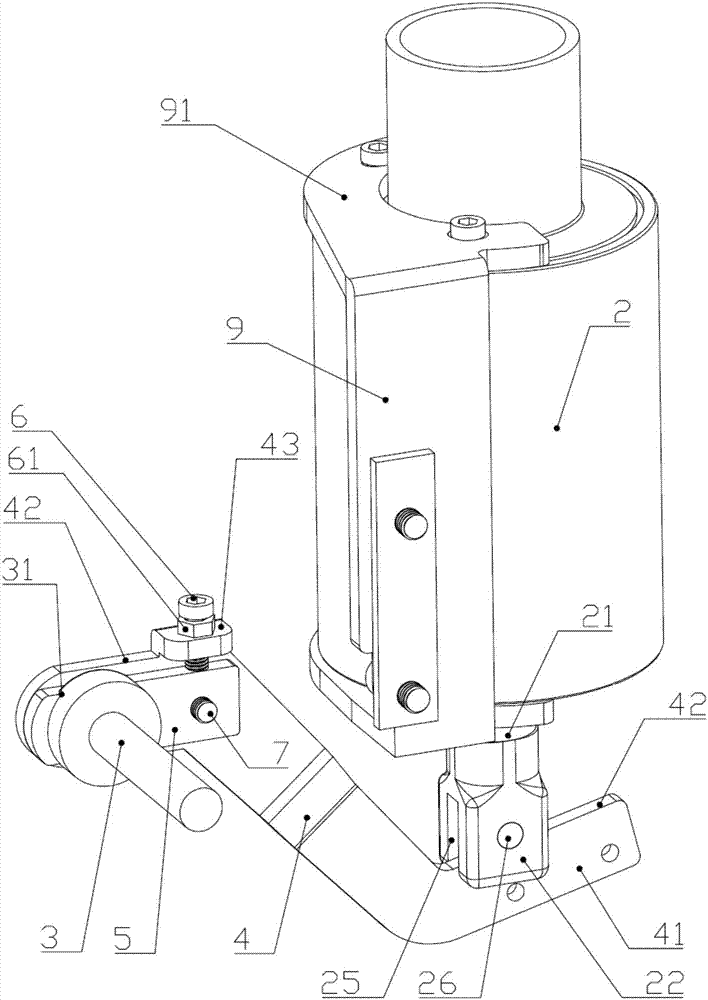
[0032] Embodiment one: if Figure 1-7 As shown, a sewing machine presser foot lifting device includes a connecting rod assembly connected with a tie rod seat 3, and is characterized in that: one end of the connecting rod assembly is connected to the outer end of the tie rod seat, and the connecting rod assembly The other end leans against the driver 2; the connecting rod assembly at least includes a lifting and pressing connecting rod 4, and the two ends of the lifting and pressing connecting rod 4 are respectively formed with abutting parts 41 and adjusting parts 42, and one side of the adjusting part 42 is connected with a movable The adjuster 6 for changing the initial angle of the tie rod seat 3 ; the upper end surface of the abutting portion 41 abuts against the lower end of the driver 2 .

[0033] Preferably, the connecting rod assembly also includes an adjusting member 5 arranged between the adjusting portion 42 and the rod base 3, the adjusting member 5 is fixed on one...


PUM


Abstract

The invention discloses a sewing machine foot pressing and lifting device and belongs to the technical field of sewing machines. The sewing machine foot lifting device comprises a drive as well as a foot pressing mechanism, wherein the drive is fixedly arranged on one side of a sewing machine shell; the foot pressing mechanism comprises a pull rod base which is fixedly arranged on one side of thesewing machine shell and is used for adjusting a foot pressing height; an adjusting groove is formed in the pull rod base; a lifting connecting rod is arranged at the lower end part of the drive; a propping part and an adjusting part are respectively formed at two ends of the lifting connecting rod; the drive is propped against the propping part; an adjusting component is arranged between the adjusting part and the pull rod base; the adjusting component is hinged with the adjusting part; the adjusting component is matched with the adjusting groove and is clamped inside the adjusting groove; apressure regulator is arranged on one side of the adjusting part in a lifting manner; the pressure regulator is propped against the upper end part of the adjusting part. As the lifting height of a sewing machine foot pressing part is adjusted in a stepless manner, a common sewing machine can be transformed into an automatic thread cutting sewing machine conveniently.

Description

technical field [0001] The invention belongs to the technical field of sewing machines, in particular to a sewing machine presser foot lifting device. Background technique [0002] At present, the interlock sewing machine: commonly known as the interlock sewing machine, uses two kinds of sutures, needle and shuttle, to make the shuttle thread form a single-sided covering chain stitch on the bottom of the sewing material, or add a covering line to the front of the sewing material to form a double-sided covering chain. Stitch, an industrial sewing machine that sews two or more layers of material. It is also an industrial sewing machine that can sew two or more layers of sewing materials. The covering line on the front is mainly for aesthetic decoration. Interlock sewing machine has greater elasticity due to the covered chain stitches sewn, which can be stretched when the garment is worn and restored after wearing, so it is suitable for sewing knitted garments that are worn n...

Claims


Application Information

Patent Timeline
Patent Type & Authority Applications(China)
IPC IPC(8): D05B29/02D05B65/00D05B69/02D05B69/10
CPCD05B29/02D05B65/00D05B69/02D05B69/10
Inventor 周善足蒋达淼
Owner 台州市速普机电有限公司
Why Eureka
Try Eureka