Eccentric pin structure

An eccentric pin and eccentric technology, which is applied in the direction of connecting components, rods, bolts, etc., can solve the problems of complex angle adjustment and weak bearing capacity, and achieve high adjustment accuracy, strong bearing capacity, and the effect of avoiding torque loss

Active Publication Date: 2018-04-24
DONGFENG COMML VEHICLE CO LTD
View PDF9 Cites 4 Cited by
  • Summary
  • Abstract
  • Description
  • Claims
  • Application Information

AI Technical Summary

Problems solved by technology

[0007] The purpose of the present invention is to overcome the problems of complicated angle adjustment and weak bearing capacity existing in the prior art, and provide an eccentric pin structure with convenient angle adjustment and strong bearing capacity

Method used


Image

  • Eccentric pin structure
  • Eccentric pin structure
  • Eccentric pin structure

Examples


Embodiment 1

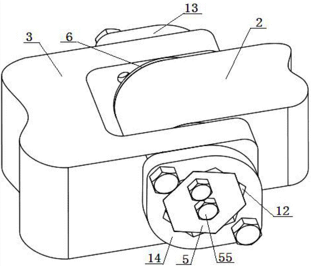
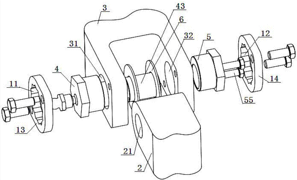
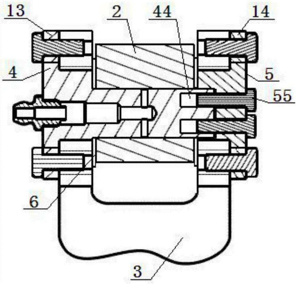
[0059] An eccentric pin structure, comprising a connecting rod 2 and a connecting fork 3, the connecting rod 2 is connected with the connecting fork 3 through an eccentric connection mechanism 1; A pin body fixing hole 31 and a pin cover fixing hole 32 are oppositely arranged; the eccentric connection mechanism 1 includes an eccentric pin 4 and an eccentric pin cover 5, and a second locking pin is provided on the side of the pin cover fixing hole 32 on the connecting fork 3 Hole 12, one end of the eccentric pin cover 5 is limitedly matched with the second locking hole 12, the other end of the eccentric pin cover 5 is inserted into the pin cover fixing hole 32, and the side of the pin body fixing hole 31 on the connecting fork 3 There is a first locking hole 11 in the upper part, and one end of the eccentric pin 4 is limitedly matched with the first locking hole 11, and the other end of the eccentric pin 4 passes through the pin body fixing hole 31 and the pin hole 21 in sequenc...

Embodiment 2

[0062] Embodiment 2 is basically the same as Embodiment 1, and its difference is:

[0063] The eccentric pin 4 includes a locking cap 41, a pin seat 42 and a pin body 43 of an integral structure, the locking cap 41 is fixedly connected with the pin body 43 through the pin seat 42, and the locking cap 41 is the same as the pin seat 42. Shaft setting, the distance between the central axis of the pin body 43 and the central axis of the pin seat 42 is a millimeter, and a is greater than zero;

[0064] The locking cap 41 is limitedly matched with the first locking hole 11, the pin seat 42 is inserted into the pin body fixing hole 31, and the end of the pin body 43 near the pin seat 42 is inserted into the pin hole 21. The end of the pin body 43 far away from the pin seat 42 is fixedly connected with the eccentric pin cover 5 through a fixing bolt 55, and the diameter of the pin body 43 is 60 mm; the eccentric pin cover 5 includes a locking cover 51 and a pin cover seat 52 of an int...

Embodiment 3

[0066] Embodiment 3 is basically the same as Embodiment 2, and its difference is:

[0067] The first locking hole 11 is opened on the first locking plate 13, and the first locking plate 13 is fixedly connected with the connecting fork 3 by at least two bolts; the second locking hole 12 is opened on the second On the locking disc 14, the second locking disc 14 is fixedly connected to the connecting fork 3 by at least two bolts.


PUM


Abstract

An eccentric pin structure comprises a connecting rod and a connecting fork. The connecting rod is connected with the connecting fork through an eccentric connecting mechanism, a pin hole is formed inthe connecting rod, a pin fixing hole and a pin cover fixing hole are oppositely formed in the connecting fork, the eccentric connecting mechanism comprises an eccentric pin and an eccentric pin cover, a second locking hole is formed in the side of the pin cover fixing hole in the connecting fork, one end of the eccentric pin cover is matched with the second locking hole in a limited manner, theother end of the eccentric pin cover is matched with the pin cover fixing hole in an inserted manner, a first locking hole is formed in the side of the pin fixing hole in the connecting fork, one endof the eccentric pin is matched with the first locking hole in a limited manner, and the other end of the eccentric pin sequentially penetrates the pin fixing hole and the pin hole and then is fixedlyconnected with the eccentric pin cover through a fixing bolt. The eccentric pin structure is firm in connection, excellent in radial bearing capacity, small in arrangement space and high in adjustment precision.

Description

technical field [0001] The invention relates to an eccentric connection structure, in particular to an eccentric pin structure, which is particularly suitable for improving the bearing capacity of the connection structure and reducing the axial installation size. Background technique [0002] The common eccentric pin structure is the eccentric bolt, which generally includes two eccentric locking plates, an eccentric bolt and a nut. This structure has the advantages of simple structure and simple manufacturing and assembly process. However, its radial bearing capacity is small, and the axial installation size is relatively large, so it is not suitable for the large radial load rotating pair structure. For example, the front suspension structure of some medium and heavy commercial vehicles currently adopts double wishbone suspension, and the traditional eccentric bolts cannot meet the large load requirements of the suspension. [0003] The Chinese patent publication number is...

Claims


Application Information

Patent Timeline
Patent Type & Authority Applications(China)
IPC IPC(8): F16B7/20F16B19/02
CPCF16B7/20F16B19/02
Inventor 刘向邵雄徐琰玮
Owner DONGFENG COMML VEHICLE CO LTD
Why Eureka
Try Eureka