
High-efficiency energy-efficient P+N channel drive circuit

A drive circuit, energy-saving technology, applied in the field of high-efficiency and energy-saving P+N channel drive circuits, can solve the problems of high power consumption, inability to meet the requirements of high-efficiency switching and low power consumption, and low efficiency, and achieve low Power consumption, the effect of satisfying high-efficiency switching

Pending Publication Date: 2018-04-24
INTEMOTION TECH WUXI
View PDF13 Cites 3 Cited by
  • Summary
  • Abstract
  • Description
  • Claims
  • Application Information

AI Technical Summary

Problems solved by technology

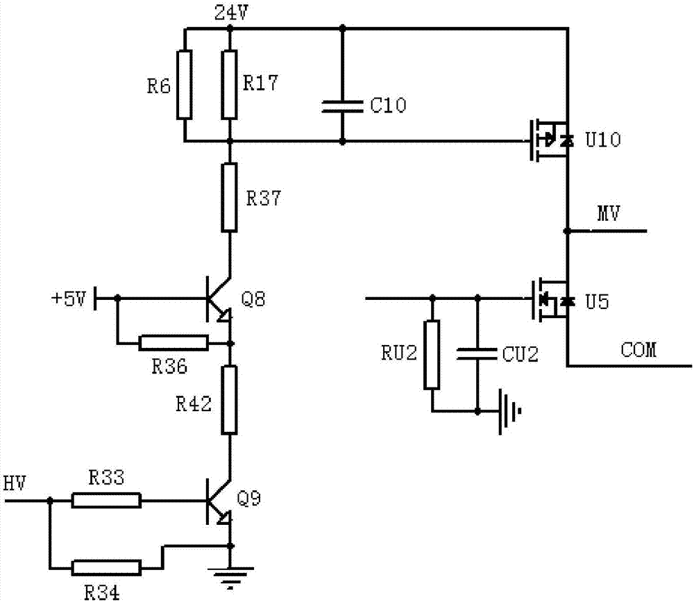
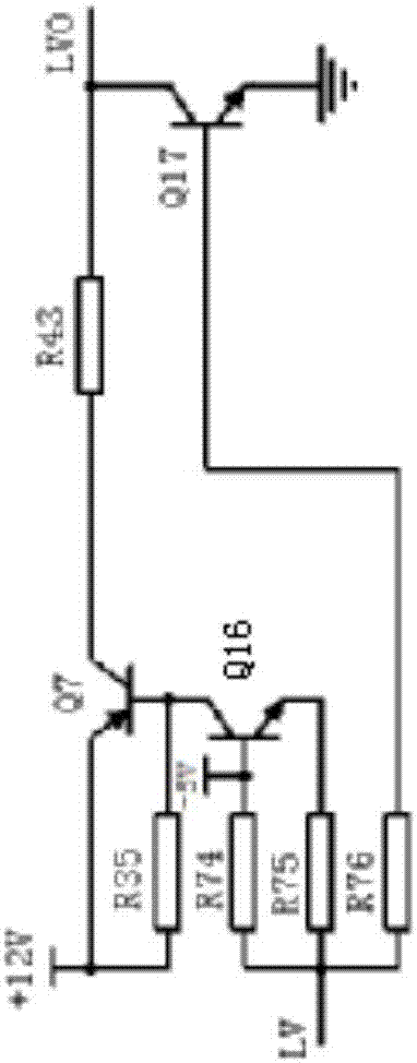
[0002] At present, the traditional P+N drive circuit generally has the problems of high power consumption and low efficiency, such as figure 1 and figure 2 As shown, the upper bridge part of the P+N channel drive circuit used in traditional motor drive includes resistor R33, resistor R34, transistor Q9, resistor R42, resistor R36, PNP transistor Q8, resistor R37, resistor R6, resistor R17 , Capacitor C10, P channel MOS tube U10; the lower bridge part includes resistor R35, resistor R74, resistor R75, resistor R76, PNP transistor Q7, resistor R43, NPN transistor Q16, NPN transistor Q17, N communication MOS tube U5 , resistor RU2 and capacitor CU2
When the HV level is high, the transistor Q9 is turned on. If you want to quickly turn on the P-channel MOS transistor U10, you need to reduce the resistance of the resistor R37, and then reduce the resistance of other voltage dividing resistors such as the resistor R6 and the resistor R17. Small size will eventually lead to severe heating of the resistor, high power consumption, and serious energy waste. Moreover, the higher the switching frequency of the drive circuit, the smaller the resistance value of the voltage dividing resistor, resulting in greater power consumption, which cannot meet the needs of high-efficiency switching and high-efficiency switching at the same time. low power requirements

Method used


Image

  • High-efficiency energy-efficient P+N channel drive circuit
  • High-efficiency energy-efficient P+N channel drive circuit
  • High-efficiency energy-efficient P+N channel drive circuit

Examples


Embodiment Construction

[0013] In order to facilitate the understanding of the present invention, the present invention will be described more fully below with reference to the relevant drawings. The preferred embodiments of the invention are shown in the drawings. However, the present invention can be implemented in many different forms and is not limited to the embodiments described herein. On the contrary, the purpose of providing these embodiments is to make the disclosure of the present invention more thorough and comprehensive. It should be noted that when an element is considered to be "connected" to another element, it may be directly connected to the other element or a centered element may exist at the same time. Unless otherwise defined, all technical and scientific terms used herein have the same meaning as commonly understood by those skilled in the technical field of the present invention. The terms used in the specification of the present invention herein are only for the purpose of de...


PUM


Abstract

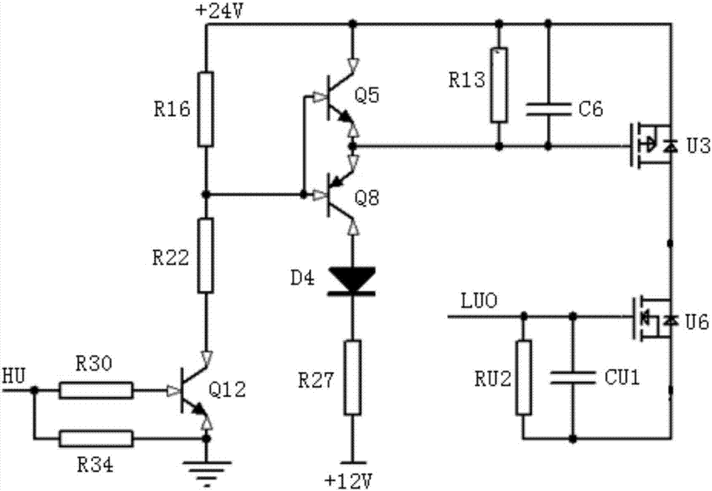
The invention discloses a high-efficiency energy-efficient P+N channel drive circuit comprising an upper bridge circuit and a lower bridge circuit; the upper bridge circuit comprises a resistor R30, aresistor R34, a NPN type triode Q12, a resistor R22, a resistor R16, a NPN type triode Q5, a PNP type triode Q8, a diode D4, a resistor R27, a resistor R13, a capacitor C6, and a P channel MOS pipe U3; the lower bridge circuit comprises a resistor R43, a resistor R44, a NPN type triode Q18, a resistor R41, a resistor 37, a NPN type triode Q16, a PNP type triode Q17, a resistor R38, a resistor R39, a diode D7, a N channel MOS pipe U6, a capacitor CU1, and a resistor RU2. When the upper bridge circuit is open, the upper bridge open voltage outputted by the upper bridge circuit power supply is charged to the lower bridge circuit for usage, and serves as the open energy of the lower bridge circuit, thus providing high-efficiency energy-efficient effects.

Description

Technical field [0001] The invention relates to the field of motor driving, in particular to a high-efficiency and energy-saving P+N channel driving circuit. Background technique [0002] At present, the traditional P+N drive circuit generally has the problems of large power consumption and low efficiency, such as figure 1 with figure 2 As shown, the upper bridge part of the P+N channel driving circuit used in the traditional motor drive includes resistor R33, resistor R34, transistor Q9, resistor R42, resistor R36, PNP transistor Q8, resistor R37, resistor R6, resistor R17 , Capacitor C10, P-channel MOS transistor U10; the lower bridge part includes resistor R35, resistor R74, resistor R75, resistor R76, PNP transistor Q7, resistor R43, NPN transistor Q16, NPN transistor Q17, N communication MOS transistor U5 , Resistor RU2 and capacitor CU2. When the HV is high, the transistor Q9 is turned on. If you want to quickly turn on the P-channel MOS transistor U10, you need to reduce...

Claims


Application Information

Patent Timeline
Patent Type & Authority Applications(China)
IPC IPC(8): H03K17/567
CPCH03K17/567H03K2217/0036H03K2217/0081
Inventor 娄晶谷建明芮宽
Owner INTEMOTION TECH WUXI
Learn More