Oil way system of closed type transmission mechanism

A technology of oil circuit system and transmission mechanism, applied in transmission parts, mechanical equipment, belts/chains/gears, etc., can solve the problems of increasing the wear of sliders and slide rails, waste of resources, and cumbersomeness, so as to avoid loss and overflow. , the effect of reducing temporary space and compact overall structure

Pending Publication Date: 2018-04-27
广东凯宝机器人科技有限公司
View PDF0 Cites 2 Cited by
  • Summary
  • Abstract
  • Description
  • Claims
  • Application Information

AI Technical Summary

Problems solved by technology

[0003] During the long-term use of the transmission mechanism, the lubricating oil in the transmission mechanism will gradually lose with the number of uses and time. If the lubricating oil is not added in time, the friction and wear between the transmission parts will increase, which will affect the performance of the transmission parts. The service life and transmission efficiency will affect the production efficiency. In the process of adding lubricating oil to the transmission mechanism, the staff must first disassemble the transmission mechanism, then take out the transmission parts, and then add lubricating oil to it. The steps are extremely cumbersome , improve the working intensity of the staff, and the process of manually adding lubricating oil is likely to cause the overflow and loss of lubricating oil, resulting in waste of resources and pollution of the surrounding environment; the existing transmission mechanism generally only has one slider, resulting in slider The design becomes heavy and wide, and increases the wear between the slider and the slide rail, affecting its service life

Method used


Image

  • Oil way system of closed type transmission mechanism
  • Oil way system of closed type transmission mechanism
  • Oil way system of closed type transmission mechanism

Examples


Embodiment Construction

[0024] In order to facilitate the understanding of those skilled in the art, the present invention will be further described with reference to the following examples, and the content mentioned in the embodiments is not a limitation of the present invention.

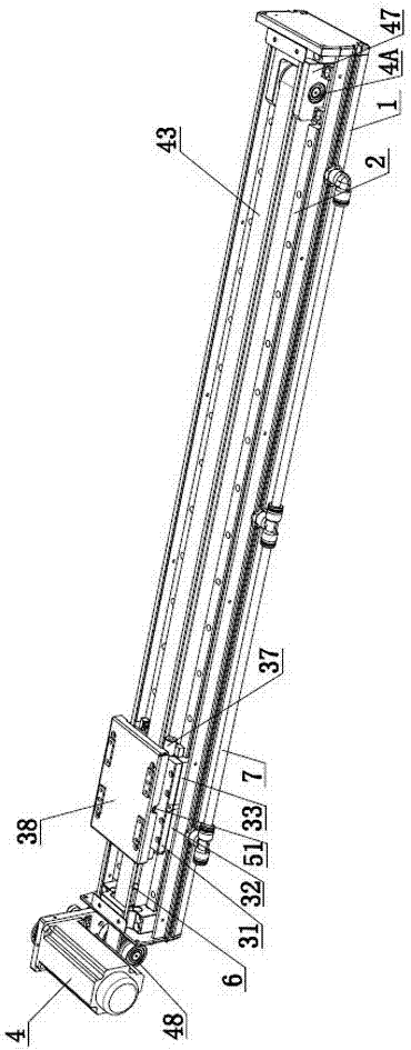
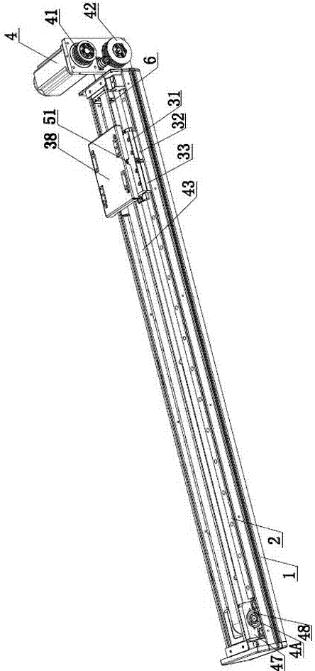
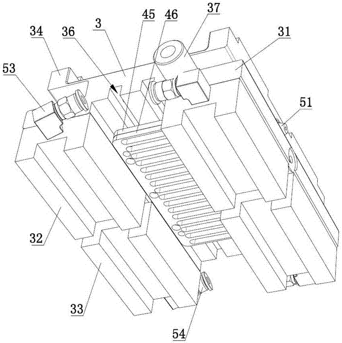
[0025] Such as Figure 1 to Figure 6 Shown is the first embodiment of an oil circuit system of a closed transmission mechanism of the present invention, which includes a base 1, a guide rail installed on the base 1, a sliding seat 3 provided on the guide rail 2, and a drive that drives the sliding seat 3 to move back and forth Mechanism, both sides of the sliding seat 3 are equipped with mounting seats 31, and the mounting seats 31 on both sides are equipped with a first sliding block 32 and a second sliding block 33, which are used to provide the first sliding block 32 and The oil path system 5 provided by the second slider 33 and the sliding table 34 installed on the sliding seat 3; the oil path system 5 includes a first oi...


PUM


Abstract

The present invention relates to the technical field of automation equipment, in particular to an oil circuit system of a closed transmission mechanism, which includes a base, a guide rail installed on the base, a sliding seat on the guide rail, and a driving mechanism for driving the sliding seat to move back and forth. Both sides of the slider are equipped with mounting seats, and the mounting seats on both sides are equipped with a first slider and a second slider, and oil passages for supplying oil to the first slider and the second slider. system and a sliding table installed on the sliding seat; the oil circuit system includes an oil inlet nozzle arranged on the side of the sliding table, a splitter joint connected to the oil inlet nozzle and arranged on the sliding seat, and a first splitter nozzle communicated with one end of the splitter joint And the second flow nozzle communicated with the other end of the flow connection. In the present invention, the design of the oil circuit system greatly facilitates the staff to add lubricating oil to the first slider and the second slider; the design of the first slider and the second slider not only reduces the temporary space, but also makes the overall The structure becomes more compact, and the service life is effectively extended.

Description

Technical field [0001] The invention relates to the technical field of automation equipment, in particular to an oil circuit system of a closed transmission mechanism. Background technique [0002] The transmission mechanism is widely used in the fields of mechanical devices and woodworking machinery. It usually includes a guide rail and a slider, wherein the slider is slidably fixed on the guide rail. [0003] During the long-term use of the transmission mechanism, the lubricating oil in the transmission mechanism will gradually lose with the frequency and time of use. If the lubricating oil is not added in time, the friction and wear between the transmission components will increase, thereby affecting the transmission components. The service life and transmission efficiency affect production efficiency. In the process of adding lubricating oil to the transmission mechanism, the staff must first disassemble the transmission mechanism, then take out the transmission components, and...

Claims


Application Information

Patent Timeline
Patent Type & Authority Applications(China)
IPC IPC(8): F16H57/04
CPCF16H57/042F16H57/0489F16H57/0497
Inventor 蒋凯
Owner 广东凯宝机器人科技有限公司
Why Eureka
Try Eureka