Icing sensor

An icing sensor and heater technology, applied in the sensor field, can solve the problems of loss of controllability, asymmetry of lift and tension, poor reliability, etc., and achieve the effects of reducing mental burden, not easy to fatigue and cracking, and long service life

Active Publication Date: 2018-04-27
CHINA HANGFA SOUTH IND CO LTD
View PDF4 Cites 2 Cited by
  • Summary
  • Abstract
  • Description
  • Claims
  • Application Information

AI Technical Summary

Problems solved by technology

Ice and snow on the wings are easy to be observed, but maintenance work is common; engine intake icing is difficult to observe with the naked eye, and it comes and goes without a trace, and has not received enough understanding and attention
[0004] At present, the anti-icing pressure signaler of turboprop engine is still a mechanical signaler with air pressure bellows and contact switch, which has low sensitivity, sluggish response and poor reliability.
The crew must closely observe the flashing indicator light of the old-fashioned anti-icing pressure signal device, so as to judge the timing of opening the air intake guide to heat the air supply electric mechanism, which is not conducive to flight safety
There are mechanical contact switches inside the anti-icing knob and the heating and air supply electric mechanism of the air intake guide. Poor contact of the contact switches will cause the anti-icing system to fail
Although a transport aircraft is equipped with four turboprop engines, one engine is only equipped with an anti-icing pressure signal device and an air intake guide warming air supply electric mechanism. If a mechanical contact switch fails, it may cause The deicing progress of the left and right wings of the transport aircraft is not synchronized, resulting in asymmetric lift and pulling forces and entering a stall spiral
Preliminary statistics show that up to now, all the crashes of transport aircraft have been caused by bad weather, flying into cumulonimbus clouds, freezing of the engine inlet or the leading edge of the wing or the leading edge of the tail, and the loss of control performance and crash

Method used


Image

  • Icing sensor
  • Icing sensor

Examples


Embodiment Construction

[0016] In order to have a clearer understanding of the technical features, purposes and effects of the present invention, the specific implementation manners of the present invention will now be described with reference to the accompanying drawings. Wherein, the same parts adopt the same reference numerals.

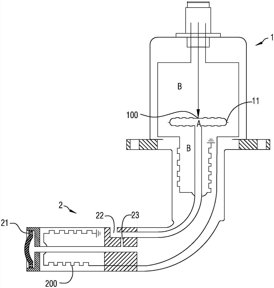
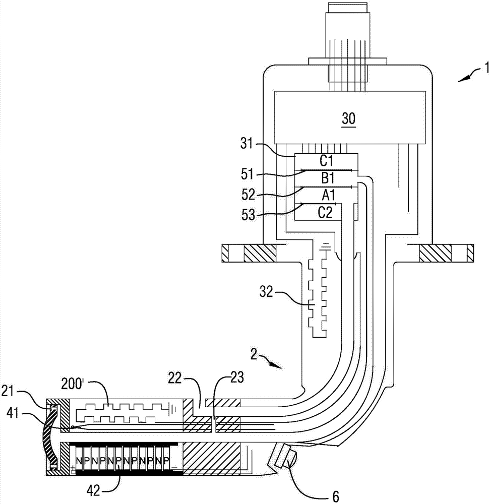
[0017] figure 2 It is a schematic diagram of the structure and principle of the icing sensor according to a specific embodiment of the present invention; see figure 2 As shown, the present invention provides a kind of icing sensor, which includes a base 1 and an elbow 2 connected to each other, and the end of the elbow 2 is provided with 20 air inlet holes 21 with a diameter of 0.7mm. The side wall of the elbow 2 is provided with 8 static pressure holes 22 with a diameter of 2.5mm. The base 1 is provided with a controller 30, a pressure chamber 31, and a tube root heater 32. The inside of the elbow 2 is provided with The thermal resistance temperature measuring elemen...


PUM

PropertyMeasurementUnit
diameteraaaaaaaaaa
diameteraaaaaaaaaa

Abstract

An icing sensor comprises a base and an elbow which are mutually connected, wherein the base is internally provided with a controller, a pressure chamber and a tube root heater; the elbow is internally provided with a thermal resistance thermometer, a refrigeration element and a tube head heater; the pressure chamber is internally provided with a first vacuum chamber, a dynamic pressure chamber, astatic pressure chamber and a second vacuum chamber sequentially; a total pressure sensor silicon diaphragm is arranged between the first vacuum chamber and the dynamic pressure chamber; a differential pressure sensor silicon diaphragm is arranged between the dynamic pressure chamber and the static pressure chamber; and a static pressure sensor silicon diaphragm is arranged between the static pressure chamber and the second vacuum chamber. The icing sensor provided in the invention has the advantages of high sensitivity, good reliability and long service life. Through arranging the bismuth telluride semiconductor refrigeration element, the refrigeration amount can be controlled, icing is earlier than inlet guide vane icing, and icing damages can be predicted.

Description

technical field [0001] The invention relates to the technical field of sensors, in particular to an icing sensor used for an air intake of a turboprop engine. Background technique [0002] my country's medium-sized turboprop transport aircraft is imitated and improved from the An-12 transport aircraft. Due to backward design technology, its safety and reliability performance lags behind the American C-130 medium-sized transport aircraft of the same level. It has crashed due to icing. [0003] In terms of deicing and anti-icing technology research, the aircraft body has received more attention than the aeroengine. Ice and snow on the wings are easy to be observed, but maintenance work is common; engine intake icing is difficult to observe with the naked eye, and it comes and goes without a trace, and has not received enough understanding and attention. [0004] At present, the anti-icing pressure annunciator of turboprop engine is still a mechanical annunciator with air pres...

Claims


Application Information

Patent Timeline
Patent Type & Authority Applications(China)
IPC IPC(8): G01K7/16G01L13/00G01L19/00B64D15/20
CPCB64D15/20G01K7/16G01L13/00G01L19/00
Inventor 刘飞亭方春娇陈欣贺岗
Owner CHINA HANGFA SOUTH IND CO LTD
Why Eureka
Try Eureka