
A device and method for purifying flue gas by using calcium carbide slag

A calcium carbide slag and flue gas technology, applied in chemical instruments and methods, separation methods, inorganic chemistry, etc., can solve problems affecting sulfite oxidation, in the laboratory stage, and the effect is not significant, and achieve high application value.

Active Publication Date: 2020-10-16
石嘴山市华昊化工有限公司
View PDF4 Cites 0 Cited by
  • Summary
  • Abstract
  • Description
  • Claims
  • Application Information

AI Technical Summary

Problems solved by technology

[0004] Since the main component of carbide slag is Ca(OH) 2 Therefore, many enterprises and scientific research institutes have carried out research work on desulfurization using carbide slag as raw material, but generally speaking, this work is still in the laboratory stage
One of the main reasons is that calcium carbide slag contains a certain amount of reducing ions, especially S2-, which absorbs SO 2 Not much effect, but it seriously affects the oxidation of sulfite
In response to this problem, Hangzhou Tianlan Environmental Protection Equipment Co., Ltd. proposed a method of oxidation outside the tower, and some companies also proposed to add a strong oxidant to carbide slag to oxidize sulfide, but the effect of the above method in practice is not significant

Method used


Image

  • A device and method for purifying flue gas by using calcium carbide slag
  • A device and method for purifying flue gas by using calcium carbide slag

Examples


Embodiment 1

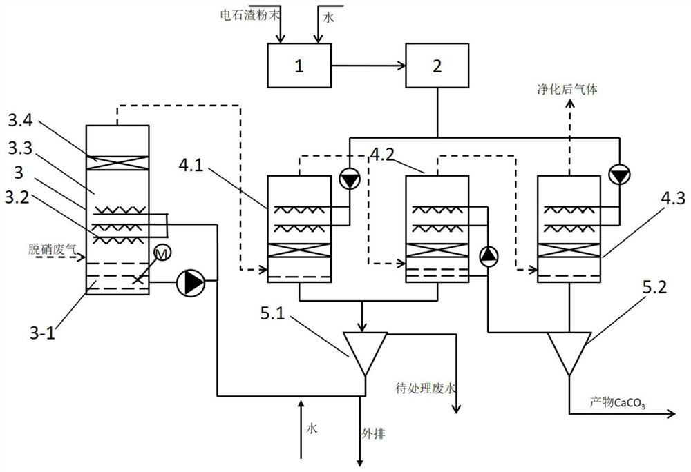
[0035] The device used in this embodiment is as figure 1 As shown, a device for purifying flue gas by using calcium carbide slag, a device for purifying flue gas by using calcium carbide slag, which includes a dissolution tank 1, a magnetic separator 2, a desulfurization tower 3, a settling tank 5, and three desulfurization tanks connected in series Carbon towers 4-1, 4-2, 4-3; desulfurization towers are provided with demisters 3-4, nozzles, tower bottom oxidation pools 3-1 in sequence from top to bottom, and tower bottom oxidation pools 3-1 pass through the external The slurry circulation pipeline is connected to the spray pipe, the top gas outlet of the desulfurization tower 3 is connected to three decarbonization towers connected in series, the inlet of the dissolution tank 1 is connected to the carbide slag powder conveying pipeline and the water supply pipeline, and the outlet of the dissolution tank 1 is connected to the magnetic separation The inlet of the magnetic sepa...

Embodiment 2

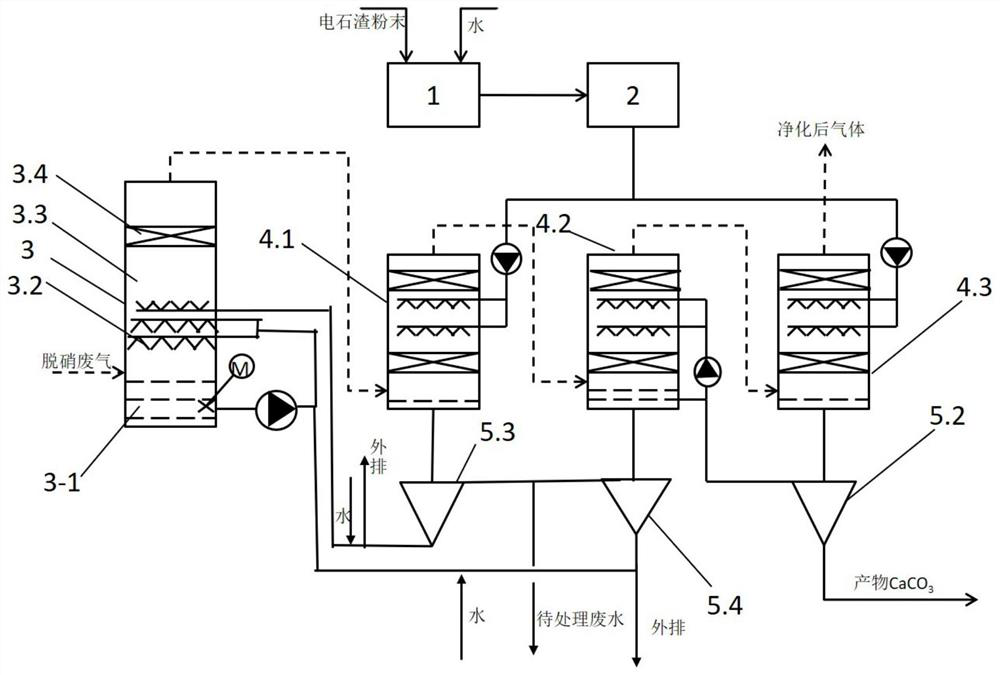
[0048] The device used in this embodiment is as figure 1 As shown, a device for purifying flue gas by using calcium carbide slag, a device for purifying flue gas by using calcium carbide slag, which includes a dissolution tank 1, a magnetic separator 2, a desulfurization tower 3, a settling tank 5, and three desulfurization tanks connected in series Carbon towers 4-1, 4-2, 4-3; desulfurization towers are equipped with demisters 3-4, injectors 3-3, sprayers 3-2, tower bottom oxidation tanks 3-1 in sequence from top to bottom , the oxidation pool 3-1 at the bottom of the tower is connected to the spray pipe through the external slurry circulation pipeline, the top gas outlet of the desulfurization tower 3 is connected to three decarbonization towers connected in series, and the inlet of the dissolution pool 1 is connected to the calcium carbide slag powder conveying pipeline and water supply Pipeline connection, the outlet of dissolution tank 1 is connected to the inlet of magne...


PUM


Abstract

The invention discloses a device and a method for purifying flue gas by using calcium carbide slag. The calcium carbide slag is firstly dissolved in water for decarbonizing so as to generate calcium carbonate, and the calcium carbonate and reducing substances in the calcium carbide slag are separated from each other by means of a sedimentation effect of a sedimentation tank; finally, the calcium carbide slag is introduced into a desulfurization tower for desulfurizing or discharging outside. Due to the reasonable process design, the device and the method fundamentally avoid the problem that the reducing substances in the calcium carbide slag disturb oxidation of calcium sulfite generated after the desulfurization.

Description

technical field [0001] The present application relates to a flue gas treatment device and method, in particular to a device and method for purifying flue gas by using carbide slag as raw material. Background technique [0002] The country pays more and more attention to environmental protection, and the development of SO 2 The governance work has become an important task of the current thermal power plants. my country's major factories, especially thermal power plants, started late in the desulfurization of flue gas. There are still relatively few mature desulfurization technologies, and most of them are still in the stage of accumulating engineering experience. Whether using CaCO 3 , CaO or Ca(OH) 2 , the common principle is through chemical reaction to make calcium element Ca(OH) 2 Form and SO in flue gas 2 reaction to generate CaSO 3 and CaSO 4 . [0003] And with Ca(OH) 2 Carbide slag, the main component, is produced in large quantities in many large and medium-...

Claims


Application Information

Patent Timeline
Patent Type & Authority Patents(China)
IPC IPC(8): B01D53/75B01D53/80B01D53/62B01D53/50B01D53/73C01F11/46
CPCB01D53/502B01D53/62B01D53/73B01D53/75B01D53/80B01D2251/20B01D2251/404B01D2251/604B01D2251/606B01D2258/0283C01F11/464
Inventor 李雪琴
Owner 石嘴山市华昊化工有限公司
Learn More