Pneumatic stirring mixing sludge automatic reflux domestic sewage purification treatment device

A technology of mixing sludge and automatic return flow, which is applied in water/sludge/sewage treatment, biological treatment equipment, biological water/sewage treatment, etc., to achieve the effects of easy promotion, simple operation and maintenance, and simplified structure

Active Publication Date: 2018-05-01
北京中立鸿环境技术有限公司
View PDF5 Cites 3 Cited by
  • Summary
  • Abstract
  • Description
  • Claims
  • Application Information

AI Technical Summary

Problems solved by technology

[0003] In order to solve the technical problem of effectively mixing and contacting microorganisms and pollutants without installing mechanical stirring facilities in the existing sewage purification tanks, the present invention provides a mixing and stirring system that achieves anaerobic and anoxic regions by pneumatic means. Sludge backflow, sewage purification treatment device without flow dead angle, so as to improve the purification treatment capacity per unit volume

Method used


Image

  • Pneumatic stirring mixing sludge automatic reflux domestic sewage purification treatment device
  • Pneumatic stirring mixing sludge automatic reflux domestic sewage purification treatment device
  • Pneumatic stirring mixing sludge automatic reflux domestic sewage purification treatment device

Examples


Embodiment 1

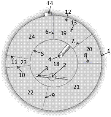
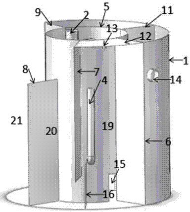
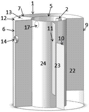
[0023] A pneumatic mixed sludge automatic backflow domestic sewage purification treatment device adopts a cylindrical cylindrical structure device, such as figure 1 As shown, it includes a cylindrical outer wall 1, the inner center of the outer wall 1 is provided with an inner cylinder 5, and the annular groove between the inner cylinder 5 and the outer wall 1 is provided with six partitions, namely the first partition 6, the second partition Plate 7, third partition 8, fourth partition 9, fifth partition 10 and sixth partition 11, the six partitions divide the annular groove into anaerobic tank 19, anoxic tank 20, aerobic tank in turn 21. The sedimentation tank 22, the dosing tank 23 and the clear water tank 24, the interior of the inner cylinder 5 is the water inlet tank 18, and the lower end of the water inlet tank 18 has a water inlet 15 that communicates with the anaerobic tank 19, and the water inlet 15 is far away from the anoxic tank 20. At one end, the anaerobic tank ...


PUM


Abstract

The invention relates to a pneumatic stirring mixing sludge automatic reflux domestic sewage purification treatment device. The pneumatic stirring mixing sludge automatic reflux domestic sewage purification treatment device comprises an inner cylinder and an outer cylinder; the inner cylinder is a water inlet tank; the space between the inner cylinder and the outer cylinder is divided into an anaerobic tank, an anoxic tank, an aerobic tank, a precipitation tank, a dosing tank and a clean water tank sequentially by partition plates; to-be-treated sewage enters the water inlet tank from the topend; a water inlet in the lower end of the water inlet tank is communicated with the anaerobic tank and the water inlet is formed in one end far away from the anoxic tank; the anaerobic tank, the anoxic tank, the aerobic tank, the precipitation tank, the dosing tank and the clean water tank are communicated with each other sequentially in a fold line manner according to the sequence of bottom, topand bottom; the top of the clean water tank is connected with a water outlet pipeline; the top of the anaerobic tank is sealed and connected with an air-blowing port; and a U-shaped pipe is arrangedon the inner cylinder between the water inlet tank and the anaerobic tank. A gas pump blows air into the anaerobic tank to descend the water level of the anaerobic tank, and the U-shaped pipe releasesenergy to realize stirring and mixing of the anaerobic tank and the anoxic area as well as refluxing of anoxic sludge towards the anaerobic tank, so the denitrification effect of a small sewage purification tank is improved, and the purification and treatment speed of the sewage is increased; and the device is not provided with a power stirring facility, so the device is simple to operate and maintain and convenient to apply and popularize.

Description

technical field [0001] The invention relates to a sewage treatment facility, in particular to a dispersed domestic sewage purification treatment device. Background technique [0002] In the process of decentralized sewage treatment in rural areas or some cities and towns, there is a lack of a treatment facility with a simple structure, low energy consumption, and efficient removal of organic pollutants and denitrification and phosphorus removal at the same time. Most of the existing small sewage purification tanks use aeration method to degrade organic matter in sewage through aerobic microbial process to remove organic pollutants and ammonia nitrogen in sewage. However, small sewage purification tanks usually have large flow dead zones in anaerobic or anoxic areas because there is no mechanical stirring and sludge return equipment, and it is difficult for anaerobic microorganisms to function effectively, resulting in poor removal of ammonia nitrogen and total nitrogen, espe...

Claims


Application Information

Patent Timeline
Patent Type & Authority Applications(China)
IPC IPC(8): C02F9/14
CPCC02F1/52C02F3/305C02F9/00C02F2203/006C02F2209/42
Inventor 杨晓进尹利君佟艳明候瑷瑛
Owner 北京中立鸿环境技术有限公司
Why Eureka
Try Eureka