

2-m-Maglitude free-piston-driven high-enthalpy shock tunnel
A piston-driven, shock-wave wind tunnel technology, applied in the field of high-enthalpy shock-wave wind tunnels, can solve problems such as inability to reproduce
Active Publication Date: 2018-05-01
CHINA ACAD OF AEROSPACE AERODYNAMICS
View PDF5 Cites 35 Cited by
- Summary
- Abstract
- Description
- Claims
- Application Information
AI Technical Summary
Problems solved by technology
The high-temperature effect brought about by ultra-high-speed flow cannot be reproduced in conventional "cold" state hypersonic ground equipment
Method used
View moreImage
Smart ImageViewing Examples

Examples
Embodiment
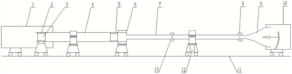
[0059] A free-piston shock tunnel, such as figure 1 As shown, it includes high-pressure gas storage chamber 1, piston launch mechanism 2, piston 3, compression tube 4, piston stop mechanism 5, main clamping mechanism 6, shock tube 7, small clamping mechanism 8, nozzle 9, test Section 10, track 11 and support system 12.
[0060] The operation process of the high enthalpy shock tunnel is described in detail.
Login to View More PUM
| Property | Measurement | Unit |
|---|---|---|
| The inside diameter of | aaaaa | aaaaa |
Abstract
A 2-m-maglitude free-piston-driven high-enthalpy shock tunnel comprises a high-pressure gas storage chamber, a piston launching mechanism, a piston, a compression tube, a piston stop mechanism, a maincapsule mechanism, a shock wave tube, a small capsule mechanism, a spray tube, a test segment, a track and a support system. The high-pressure gas storage chamber is arranged at the upstream of the piston launching mechanism and stores high-pressure air. After being launched through the piston launching mechanism, the piston may move to the downstream of the compression tube at increased speed; when the piston arrives at the tail end of the compression tube, most energy is transmitted to helium-argon mixed light gas, and high-temperature high-pressure gas is generated; at this moment, a membrane of the main capsule mechanism breaks, incoming shock wave is generated and passes through the shove wave tube until its tail end, the shoe wave may be reflected, and high-temperature high-pressuregas is generated to cause breakage of a membrane of the small capsule mechanism. The high-temperature high-pressure test gas passes through the spray pipe to the test segment, and free stream conditions required are acquired.
Description
technical field [0001] The invention relates to a high-enthalpy shock wind tunnel driven by a 2m-level free piston, which can not only study aerodynamic basic research such as ultra-high-speed high-temperature real gas effects, but also carry out engineering applications such as scramjet engines and space re-entry vehicles. Research. Background technique [0002] The wide range of flight conditions of hypersonic vehicles and the unique physical phenomena that need to be studied make a single hypersonic test equipment unable to meet the test requirements, resulting in the diversification of hypersonic test equipment. For wind tunnel tests, it is currently impossible to carry out a series of experimental studies such as aerothermodynamics, aero-optics, and aeroacoustics within the entire flight envelope, and can only evaluate the "critical path" before the flight test. In the low hypersonic region with a Mach number of 5-12, the simulation of the ideal gas flow Mach number an...
Claims
Login to View More Application Information
Patent Timeline
 IPC IPC(8): G01M9/02
CPCG01M9/02
Inventor毕志献陈星蒋博朱浩李睿劬谌君谋李辰宋可清张冰冰刘吴月马雁捷吴健
OwnerCHINA ACAD OF AEROSPACE AERODYNAMICS