Eureka AIR delivers breakthrough ideas for toughest innovation challenges, trusted by R&D personnel around the world.

Method for maintaining loop bandwidth of phase-locked loop circuit and phase-locked loop circuit debugging method

A phase-locked loop and circuit loop technology, applied in the direction of electrical components, automatic power control, etc., can solve the problems of chip power consumption and area waste, data loss, phase-locked loop data loss, etc., to solve chip power consumption and area wasteful effect

Inactive Publication Date: 2018-05-01
深圳市芯华国创半导体有限公司
View PDF9 Cites 0 Cited by
  • Summary
  • Abstract
  • Description
  • Claims
  • Application Information

AI Technical Summary

Problems solved by technology

[0008] According to the above description, when the wireless communication chip works at different frequencies, if Icp maintains a fixed value, the loop bandwidth of the phase-locked loop will change due to the change of N and Kvco. If the bandwidth of the phase-locked loop is smaller than the transmission rate of the wireless signal, will result in loss of data
[0009] In order to solve the problem of data loss caused by the narrowing of the bandwidth of the PLL, the current practice is to design the loop bandwidth of the PLL to be much larger than the data transmission rate during chip design, so as to ensure that even if the bandwidth of the PLL is reduced, it will always be greater than Data transmission rate, but it brings waste of chip power consumption and area

Method used


Image

  • Method for maintaining loop bandwidth of phase-locked loop circuit and phase-locked loop circuit debugging method
  • Method for maintaining loop bandwidth of phase-locked loop circuit and phase-locked loop circuit debugging method

Examples


Embodiment Construction

[0035] In order to make the purpose, technical solutions and advantages of the embodiments of the present invention clearer, the technical solutions in the embodiments of the present invention will be clearly and completely described below in conjunction with the drawings in the embodiments of the present invention. Obviously, the described embodiments It is a part of embodiments of the present invention, but not all embodiments. Based on the embodiments of the present invention, all other embodiments obtained by persons of ordinary skill in the art without creative efforts fall within the protection scope of the present invention.

[0036] It should be noted that, in the case of no conflict, the embodiments of the present invention and the features in the embodiments can be combined with each other. The present invention will be described in detail below with reference to the accompanying drawings and examples.

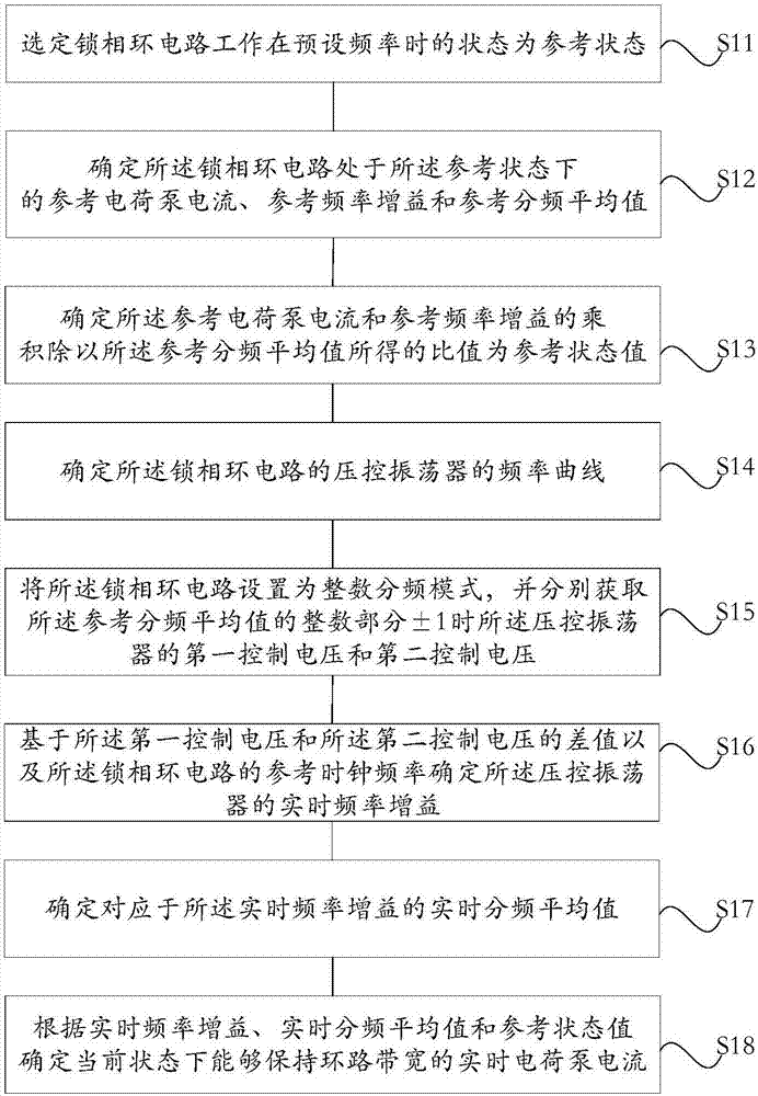
[0037] Such as figure 1 As shown, in one embodiment, the meth...


PUM


Abstract

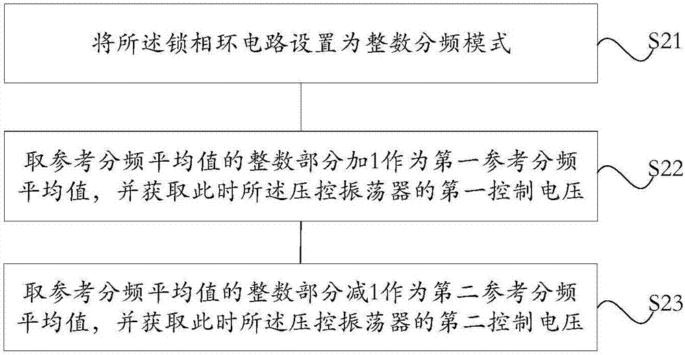
The embodiment of the invention provides a method for maintaining the loop bandwidth of a phase-locked loop circuit, which comprises the steps of determining the reference charge pump current, the reference frequency gain and a reference frequency division average value of the phase-locked loop circuit when staying at a reference state; determining a value acquired by dividing the product of the reference charge pump current and the reference frequency gain by the reference frequency division average value to be a reference state value; determining a frequency curve of a voltage-controlled oscillator of the phase-locked loop circuit; setting the phase-locked loop circuit to be an integer frequency division mode, and respectively acquiring first control voltage and second control voltage ofthe voltage-controlled oscillator when an integer part of the reference frequency division average value adds or subtracts 1; determining the real-time frequency gain of the voltage-controlled oscillator; determining a real-time frequency division average value corresponding to the real-time frequency gain; and determining the real-time charge pump current according to the real-time frequency gain, the real-time frequency division average value and the reference state value. According to the method provided by the embodiment of the invention, the loop bandwidth of the phase-locked loop circuit can be maintained to be basically constant, and a problem of data loss caused by fluctuations in loop bandwidth is solved.

Description

technical field [0001] The embodiments of the present invention relate to the technical field of electronic circuits, in particular to a method for maintaining loop bandwidth of a phase-locked loop circuit and a debugging method for a phase-locked loop circuit. Background technique [0002] Current wireless communication chips widely use frequency modulation technology for digital wireless communication, for example, common WIFI, Bluetooth and other communication chips. When the wireless communication chip adopts the frequency modulation technology, there are two ways to realize the frequency modulation from the baseband signal to the radio frequency signal: one way is to convert the digital baseband signal into an analog baseband signal through a DAC (Digital to Analog Converter), Then it is converted into a radio frequency modulation signal through the mixing operation of the analog baseband signal and the up-conversion mixer, and finally transmits it through the radio fre...

Claims


Application Information

Patent Timeline
Patent Type & Authority Applications(China)
IPC IPC(8): H03L7/099H03L7/18
CPCH03L7/0992H03L7/18
Inventor 刘锦松
Owner 深圳市芯华国创半导体有限公司
Why Eureka
Eureka Blog
Learn More