PON optical communication terminal state general survey instrument

A terminal state, optical communication technology, applied in the field of testing instruments, can solve problems such as missing and unclear user identification of optical splitter ports.

Pending Publication Date: 2018-05-01
北京益安佳光电科技发展有限责任公司
View PDF0 Cites 6 Cited by
  • Summary
  • Abstract
  • Description
  • Claims
  • Application Information

AI Technical Summary

Problems solved by technology

[0009] The optical splitter port of the PON network is the user line resource. When an existing user withdraws due to reasons such as relocation or change of service provider, the background management system platform only cancels the user account. The part of the optical cable to the user's indoor cannot be physically revoked because the port identification cannot be performed. The reason why the port identification cannot be performed is that the user identification of the optical splitter port is unclear or missing due to reasons such as the replacement of the operator and the long use of the line.

Method used


Image

  • PON optical communication terminal state general survey instrument
  • PON optical communication terminal state general survey instrument
  • PON optical communication terminal state general survey instrument

Examples


Embodiment approach 1

[0137] First, the detection device of Embodiment 1 of the present invention will be described.

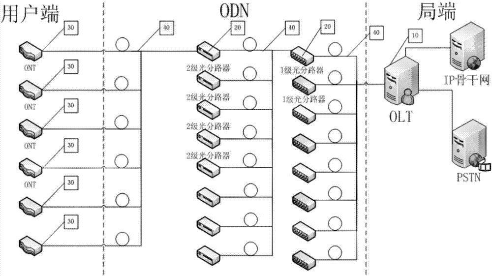
[0138] Such as figure 1 As shown, the PON optical communication network is composed of a central office OLT10, an ODN composed of a passive optical cable 40 and an optical splitter 20, and a user terminal device 30 located in the user's house; the user terminal device is figure 1 ONT in.

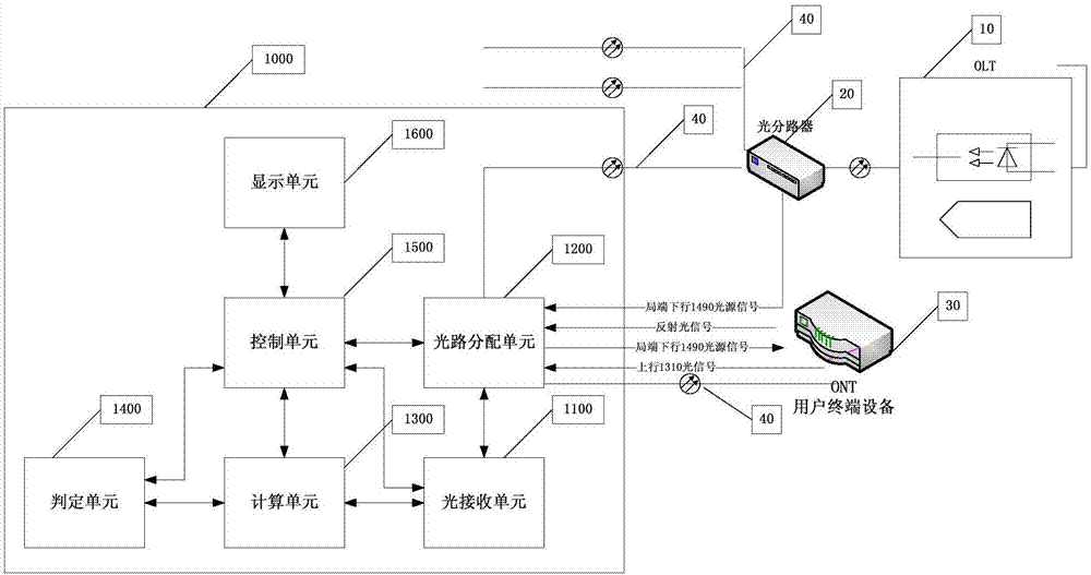
[0139] Such as figure 2 As shown, the application position of the PON terminal state detection instrument 1000 according to the present invention is illustrated, that is, the PON terminal state detection instrument according to the present invention is placed at the rear end of the optical splitter 20 near the user end, and is connected to the optical splitter 20 and the user. The terminal device 30 collects relevant signals by using the pass-through detection method, and the judgment unit 1400 makes judgments according to established judgment principles, and displays the judgment results on t...

Embodiment approach 2

[0166] Before describing in detail the second embodiment according to the present invention, briefly explain the structure and principle of the PON terminal state detection instrument according to the present invention,

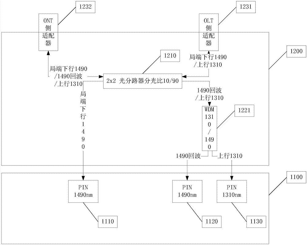
[0167] According to the PON terminal state detection instrument of Embodiment 1 of the present invention, it is combined under the following circumstances figure 2 and image 3 Note that it will lead to a decrease in the accuracy of state discrimination:

[0168] (1) When the downlink 1490 wavelength first light source signal transmitted by the local OLT10 is transmitted to the user terminal equipment 30 through the optical cable 40 and the optical splitter 20 in the ODN, the optical power value of the optical signal has abnormal attenuation, although the PON communication can be completed , but because the power of the first light source signal is low, the optical power of the first reflected signal is too low, and the detection accuracy of the second PIN1...


PUM


Abstract

The invention provides a PON optical communication terminal state general survey instrument. The PON optical communication terminal state general survey instrument is arranged at the rear end of an optical branching device of an optical distribution network (ODN) and is close to subscriber terminal equipment, and the PON optical communication terminal state general survey instrument comprises an optical receiving unit, an optical path distributing unit, a computing unit, a determination unit and a control unit. The PON optical communication terminal state general survey instrument provided bythe invention has the advantages that firstly the PON terminal state detection instrument according to the invention can carry out integrated network quality detection on all the circuits under a portof the branching device by being close to the rear end of the optical branching device of a subscriber without entering indoor space of the subscriber, so that high efficiency and timeliness of network maintenance are improved; and secondly, the PON terminal state detection instrument according to the invention adopts pass-type detection, and the subscriber is not influenced even if in Internet use, so that satisfaction degree of the subscriber in use is improved, and complaint rate of the subscriber is reduced.

Description

technical field [0001] The invention belongs to the technical field of detection instruments, and in particular relates to a PON optical communication terminal state survey instrument. Background technique [0002] Optical fiber cable is the communication medium of optical communication system. Compared with the copper cable medium in the past, it has obvious advantages such as low cost and high bandwidth, and has become the mainstream trend of communication system. FTTH (Fiber to the home, fiber to the home) As a new generation of broadband solutions, it is widely used and provides users with a high-bandwidth full-service access platform. It is an ideal service transparent network. [0003] In the specific implementation of FTTH, PON (Passive Optical Network: Passive Optical Network) eliminates outdoor active equipment because its ODN (Optical Fiber Distribution Network) does not contain electronic components and expensive active equipment, and the initial investment is sma...

Claims


Application Information

Patent Timeline
IPC IPC(8): H04B10/079H04Q11/00
CPCH04B10/07955H04Q11/0062H04Q2011/0083Y02D30/70
Inventor 王京宁
Owner 北京益安佳光电科技发展有限责任公司
Why Eureka
Try Eureka