Calibration device, method of making calibration device, and method of using calibration device

A production method and calibration technology, applied in the direction of manufacturing tools, metal processing equipment, metal processing, etc., can solve the problems of deformation of expansion joints, poor sealing effect of white iron blind plates, easy accumulation of water in expansion joints, etc., and achieve accurate and error-free installation. , The production process is simple and efficient, and the cost-saving effect

Active Publication Date: 2019-10-11
CSSC HUANGPU WENCHONG SHIPBUILDING COMPANY
View PDF5 Cites 0 Cited by
  • Summary
  • Abstract
  • Description
  • Claims
  • Application Information

AI Technical Summary

Problems solved by technology

However, the above two protection methods have their own disadvantages when installing the smoke exhaust pipe.
Disadvantages of the first method: when installing the exhaust pipe, it is necessary to temporarily install the expansion joint of the exhaust outlet of the diesel engine. After the exhaust pipe is adjusted, the expansion joint is removed and the protective blind plate is installed. This method is time-consuming It is laborious, and the installation efficiency of the exhaust pipe is low. At the same time, the expansion joint is repeatedly disassembled, and the expansion joint is easily damaged.
Disadvantages of the second method: install a white iron blind plate at the exhaust outlet of the expansion joint and the diesel engine, the sealing effect of the white iron blind plate is poor, water is easy to accumulate inside the expansion joint, and water is easy to leak into the diesel engine when the white iron blind plate is removed , and for a long time to directly use the expansion joint to adjust the exhaust pipe, it is easy to deform the expansion joint

Method used


Image

  • Calibration device, method of making calibration device, and method of using calibration device
  • Calibration device, method of making calibration device, and method of using calibration device
  • Calibration device, method of making calibration device, and method of using calibration device

Examples


Embodiment Construction

[0035] The specific implementation manners of the present invention will be further described in detail below in conjunction with the accompanying drawings and embodiments. The following examples are used to illustrate the present invention, but are not intended to limit the scope of the present invention.

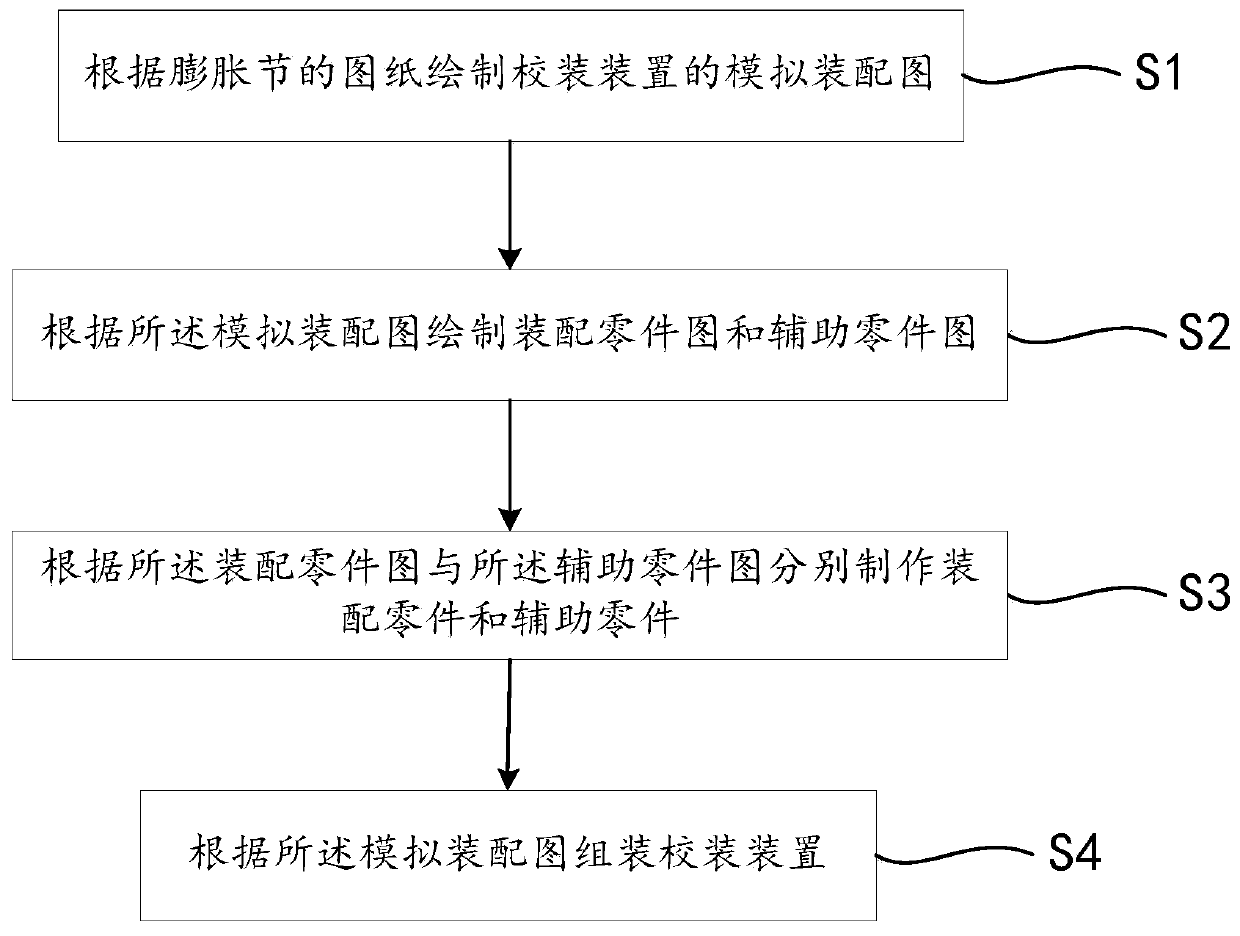
[0036] Such as figure 1 As shown, a manufacturing method of a calibration device 200 in a preferred embodiment of the present invention includes the following steps:

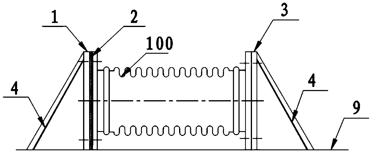
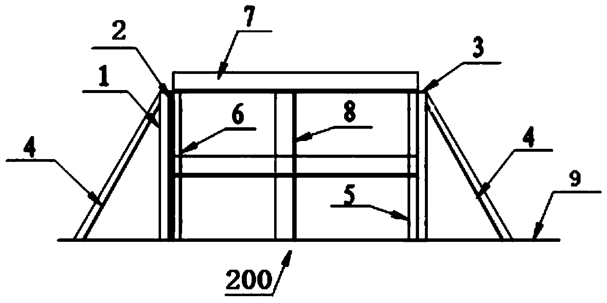
[0037] Step S1 , drawing a simulated assembly drawing of the calibration device 200 according to the drawing of the expansion joint 100 , wherein the simulated assembly drawing includes a first assembly drawing and a second assembly drawing. Such as figure 2 As shown, the first assembly drawing shows the assembly relationship between the expansion joint 100 and the first flange 1 and the second flange 3. The ports of the flue pipes are of the same size; as image 3 As shown, the second assembly diagram ...


PUM


Abstract

The invention discloses a manufacturing method of a correction device. The manufacturing method comprises the following steps that a simulated assembly drawing of the correction device is drawn according to a drawing of an expansion joint; an assembly part drawing and an auxiliary part drawing are drawn according to the simulated assembly drawing, wherein the assembly part drawing is the drawing of parts for forming the correction device, and the auxiliary part drawing is the drawing of temporary parts used when the correction device is assembled; according to the assembly part drawing and theauxiliary part drawing, assembly parts and auxiliary parts are manufactured respectively; and the correction device is assembled according to the simulated assembly drawing. The invention further discloses the correction device manufactured by the manufacturing method and a using method of the correction device. By means of the correction device, rainwater can be prevented from entering a dieselengine, a smoke exhaust pipe can be conveniently corrected, and the expansion joint can be prevented from being damaged.

Description

technical field [0001] The invention relates to the technical field of marine diesel engine installation, in particular to a calibrating device, a manufacturing method and a using method thereof. Background technique [0002] As the main power plant of a ship, the diesel engine usually takes several months from hoisting on board to complete installation of the system to meet the requirements of use. During this period, it is necessary to effectively protect the diesel engine, especially to prevent the diesel engine from entering water. There are two traditional protection methods to prevent diesel engine from water ingress: the first method is to install a flange blind plate directly at the exhaust outlet of the diesel engine; the second method is to install an expansion joint directly at the exhaust outlet of the diesel engine, and A white iron blind plate is installed at the expansion joint and the exhaust outlet of the diesel engine. [0003] Generally, when installing ...

Claims


Application Information

Patent Timeline
Patent Type & Authority Patents(China)
IPC IPC(8): B23P19/00
Inventor 陈遵清苏庆伟
Owner CSSC HUANGPU WENCHONG SHIPBUILDING COMPANY
Why Eureka
Try Eureka