A double-sided finishing fixture for large thin-walled flanges and flange processing technology

A flange and thin-walled technology, applied in the field of double-sided finishing fixtures, can solve the problem of out-of-tolerance accuracy indicators such as roundness, concentricity, flatness, parallelism, flange clamping and hoisting deformation, flatness and parallelism In order to improve the processing accuracy, overcome the deformation and processing errors, and achieve good concentricity

Active Publication Date: 2021-04-13
JIANGYIN HENGRUN RING FORGING
View PDF6 Cites 0 Cited by
  • Summary
  • Abstract
  • Description
  • Claims
  • Application Information

AI Technical Summary

Problems solved by technology

[0004] However, there are two problems in the finishing or semi-finishing machining of large thin-walled flanges using the existing lathing technology: one is that the flanges will be deformed after being clamped on the vertical lathe due to the poor rigidity of the large thin-walled flanges. A certain clamping deformation occurs. When the flange processing is completed, the elastic deformation of the flange recovers after the clamping is released, resulting in the loss of roundness, flatness and parallelism of the flange; the second is that the flange needs to process the outer circle, the inner The surface of the four positions of the hole, the upper end surface, and the lower end surface, so it needs to be clamped several times during the processing process. Face adjustment processing, etc., and the flange needs to be hoisted and turned over for surface adjustment processing
However, the large thin-walled flange itself is heavy in weight and poor in rigidity. Multiple clamping and hoisting turning over will not only reduce the processing efficiency, but also cause certain clamping and hoisting deformation of the flange, and produce two clamping The positioning error of the flange can easily lead to out-of-tolerance accuracy indicators such as roundness, concentricity, flatness, and parallelism after the final processing of the flange.

Method used


Image

  • A double-sided finishing fixture for large thin-walled flanges and flange processing technology
  • A double-sided finishing fixture for large thin-walled flanges and flange processing technology
  • A double-sided finishing fixture for large thin-walled flanges and flange processing technology

Examples


Embodiment 1

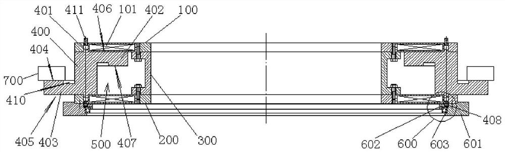
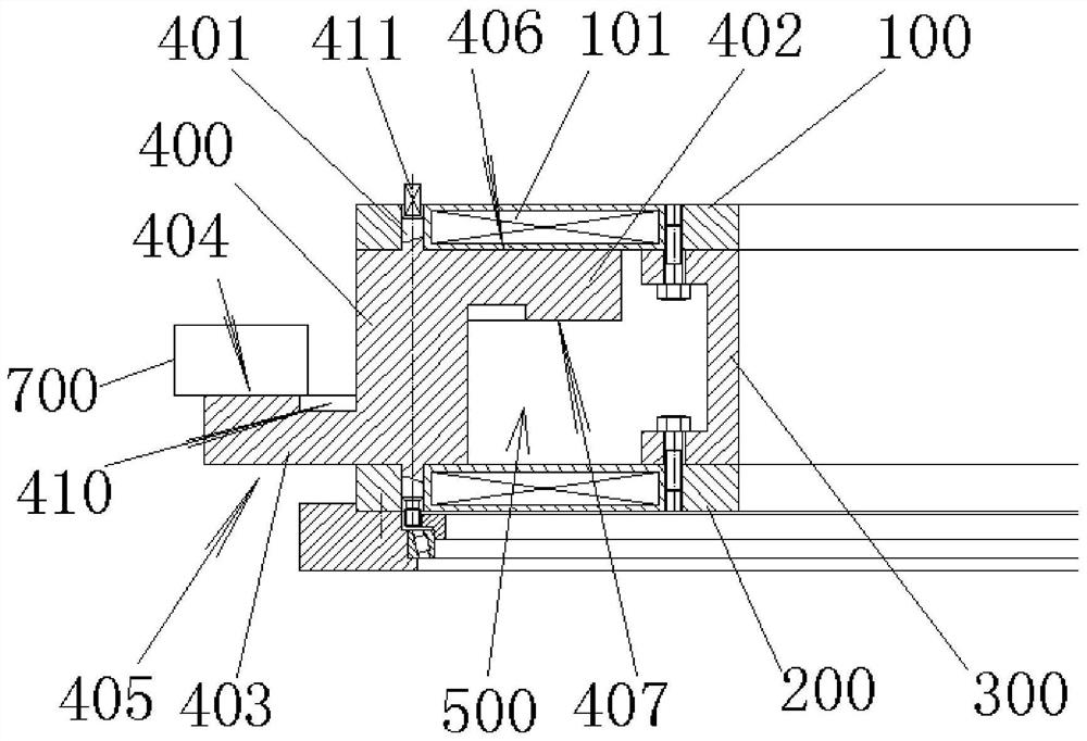
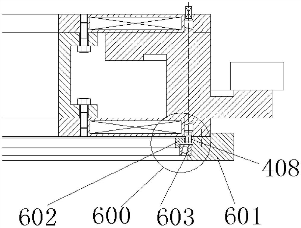
[0048] Such as Figures 1 to 6 Shown is an embodiment of a double-sided finishing fixture for a large thin-walled flange, including an upper permanent disk 100, a lower permanent disk 200, a non-magnetically conductive intermediate connecting disk 300, and several rotating positioning claws made of magnetically conductive materials 400, the upper permanent magnetic disk 100 and the lower permanent magnetic disk 200 are fixed into one body through the intermediate connecting disk 300, and an annular groove is formed between the lower end surface of the upper permanent magnetic disk, the upper end surface of the lower permanent magnetic disk, and the outer circle of the intermediate connecting disk space 500; the rotary positioning claw 400 is provided with a rotating shaft 401, an upper positioning claw 402, and a lower positioning claw 403, and the rotary positioning claw 400 is installed on the space 500 of the annular groove through the rotating shaft 401 Between the permane...

Embodiment 2

[0059] The processing technology of the double-sided finishing fixture of a large thin-walled flange of this embodiment includes the following steps:

[0060] Step 1, installing the double-sided finishing fixture of a large thin-walled flange of the embodiment on the vertical lathe workbench;

[0061] Step 2. Position the lower end face of the flange on the lower positioning claw 403, and adjust the center position of the flange;

[0062] Step 3, the magnetic force of the lower permanent magnetic disk 200 is turned on, and the magnetic force of the upper permanent magnetic disk 100 is turned off;

[0063] Step 4, finish turning the outer circle, inner hole and upper end surface of the flange;

[0064] Step 5. Place 3 temporary magnetic L-shaped stoppers on the workbench. The temporary magnetic L-shaped stoppers are distributed along the outer circle of the flange, and the temporary magnetic L-shaped stoppers are against the outer circle and lower end surface of the flange;

...


PUM


Abstract

The invention relates to the technical field of mechanical processing technology equipment, in particular to a double-sided finishing fixture for a large thin-walled flange and a flange processing technology, including an upper permanent magnetic disk, a lower permanent magnetic disk, a non-magnetically conductive intermediate connecting disk, and several guides. Rotary positioning claws made of magnetic materials, the upper permanent disk and the lower permanent disk are fixed into one body through the intermediate connection disk, and are located between the lower end surface of the upper permanent disk, the upper end surface of the lower permanent disk, and the outer circle of the intermediate connection disk. A space for an annular groove is formed; the rotary positioning claw is provided with a rotating shaft, an upper positioning claw, and a lower positioning claw, and the rotary positioning claw is installed on the upper permanent magnetic disk and the lower positioning claw of the space part of the annular groove through the rotating shaft. Between the permanent disks, the upper positioning claw and the lower positioning claw are arranged in opposite directions around the center of the rotating shaft. Adopting the present invention can realize fast switching between the positioning of the lower end face of the flange and the positioning of the upper end face of the flange without hoisting and turning over the flange, and has high processing efficiency and good processing precision.

Description

technical field [0001] The invention relates to the technical field of mechanical processing equipment, in particular to a double-sided finishing fixture for a large thin-walled flange. Background technique [0002] Flanges are widely used in industrial equipment, and the most commonly used flange material is carbon steel. In many important applications, flanges are required to have high dimensional accuracy and geometric tolerance accuracy, including better roundness of the inner and outer circles of the flange, better flatness of the flange itself, and better flatness of the flange itself. The hole and the outer circle must have better concentricity, and the upper and lower end surfaces of the flange must have better parallelism, etc. [0003] In the prior art, for the processing of large thin-walled flanges, a vertical lathe is usually used for lathe processing, specifically, a universal chuck or a special clamping tool installed on the vertical lathe workbench is used t...

Claims


Application Information

Patent Timeline
Patent Type & Authority Patents(China)
IPC IPC(8): B23Q3/00B23Q3/154B23B1/00
CPCB23B1/00B23Q3/00B23Q3/1546
Inventor 承天洋周斌卞晓磊钱伟陆飞张伟卞磊
Owner JIANGYIN HENGRUN RING FORGING
Why Eureka
Try Eureka